BILT Speaker

BILT Speaker
RevitCat - Revit Consultant
Showing posts with label workaround. Show all posts

Saturday, 26 February 2022

Poor Man's Array in Revit

There are several situations in Revit where the Array tool is not available - one of those is when using the Sketch commands.  Here is a quick workaround.

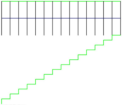
Stair Sketch Example

In this example I wanted to create a stepped side to a stair in the sketch mode.


When I selected two of the stepped boundary lines, I discovered to my horror that the Array tool is greyed out.

Workaround

Instead of using the Array tool, use the Copy tool, making sure that the 'Multiple' setting is ticked on the Options Bar

Revit first asks for the Start Point

Make sure to snap to the first end point of one of the items being copied

Then snap to the second end point

Then snap to the third end point - being the end of the first copy

Keep snapping to the end of the most recent copy until you have created your array - it is pretty quick once you get going.

In this example I had to delete the last created line

If you need a lot of copies - say 100, you have two choices:

  • Concentrate hard and try not to fall asleep
    or
  • Make 20 copies then stop and select all 20 steps;  copy those 5 times

Array Done!

I figured this trick out many years ago, and I needed it to achieve the stepped side to a stair sketch for another blog post - so I thought I'd document it in case it helps someone out there.

This might get you thinking about other uses of this simple technique.

I tried it for radial arrays, for which you would need to use the Rotate tool - but unfortunately that tool does not allow multiple copies.


Friday, 16 November 2018

Correcting the CL symbol in mirrored Revit links

The automatic 'Centreline' capability on Revit dimensions can be really annoying when they pop up unexpectedly.  But when you actually need them it is very useful to be able to just change a property of the dimension family to make the CL symbol appear.

I have seen people just placing many instances of two little pieces of overlapping text, one being C, the other L - all because they didn't know about this feature.  That is criminal!  And its a nightmare when dimensions need to be adjusted.

Mirrored Centreline Dimension Symbols

What happens when you mirror the elements and dimension?  In most situations, Revit handles it perfectly well, because the CL is a symbol family, and Revit automatically corrects the symbol orientation.  However, there is one situation where it does not work:
  • If the dimension is in a linked Revit file that has been mirrored - normally you would not see the annotation in the linked file, but if you set the view properties for that link to be 'By Linked View', then the dimensions in the mirrored linked file become visible.

  • In this situation, the symbol may not be displayed correctly, depending on how the symbol family was created:
CL symbol in Mirrored Link
  • The OOTB centreline family is actually made up of arcs and lines (not text) - this symbol does not display properly in mirrored linked files.
I was recently asked to solve this problem, so I searched high and low for settings in the dimension and in the symbol family that might solve this.  I found nothing.
  • Next I tried converting the symbol from lines to actual text in the family - I'm not sure why it was originally done as lines anyway?
  • This needs to be made up of two pieces of overlapping text - in the symbol family, not the project file.
  • In this example I made the text using a font that was clearly not lines - 'Algerian' was the first suitable windows font that I found, to make the demo clear.

  • In the original file it looks fine, as expected.
  • Once I looked at it as a mirrored linked file, another problem showed up:
  • Each letter was displayed correctly, but displaced sideways

  • Aha, it must be the text justification, I thought.
 
  • But no, that made no difference whatsoever when I tried centre, left or right Horizontal Align.  Revit is just mirroring each piece of text around the symbol centreline, then flipping the text back again around its own axis.

Weird Workaround

So what was the solution?
  • Edit the text in the symbol family - Put a space after the C and one before the L.
  • Shift the letters accordingly. 

  • It wasn't perfect to start with, so I had to shift the text around a bit, or add a second space after the L


Weird behaviour in Revit requires weird thinking workarounds!

Friday, 20 April 2018

Dynamo and Revit 2016 vs 2019

When I installed Revit 2019 recently, I uncovered a problem that will undoubtedly affect some other people - in fact there is already some buzz about this issue on the forums:


Dynamo Versions

The latest versions of Dynamo do not support Revit 2016. 
Refer to DynamoBIM blog


The theory behind this is that the Autodesk Dynamo team are working to a system whereby only three consecutive annual releases need to be supported by any version (2016, 2017, 2018  or 2017, 2018, 2019).  Typically Autodesk Revit licenses are set up that way, to only allow 3 years - but its only a license issue, not an inbuilt Revit limitation.  However, Autodesk realise that in the real world it is very difficult to manage a Revit installation in a company where you have multiple projects that need to be on different Revit versions to match up with varied consultants on each project.  Supporting 4 versions of Revit simultaneously is quite common in the industry - and Autodesk will supply licenses for this accordingly if you ask them (or your reseller).

There are two new Dynamo versions available:
  • Dynamo 1.3.3   which is virtually the same as 1.3.2, except in the versions it supports
    Dynamo 1.3.2 supports Revit 2016, 2017 & 2018 (but not 2019)
    Dynamo 1.3.3 supports Revit 2017, 2018 & 2019
  • Dynamo 2.0 is a whole new 'Major Release' - it is not backward-compatible with previous versions (dyn and dyf files are saved in a new format)
    Dynamo 2.0 supports Revit 2017, 2018 & 2019
That means there is no one version that supports both 2016 and 2019 - not even a brief overlap in time while you are updating graphs, custom nodes & packages.

Dynamo 2.0 graphs and custom nodes cannot be opened in 1.xx versions.  Some or most Dynamo 1.xx graphs and nodes will work in Dynamo 2.0 but there is no guarantee - see DynamoBIM Blog 2.0 and Beyond for more detail. 

It is possible to have two parallel installations of Dynamo 1.3.2 (or earlier) and 2.0 - both of which would run on Revit 2017 & 2018 (you get a choice of which to run when you start Dynamo) - but only one of those two versions would run on either Revit 2016 or 2019 (unless you have 1.3.3 and 2.0 which could both run on 2019).

I don't think that you can have both 1.3.2 and 1.3.3 running in parallel like this - I have not tried it, but that is the word I see on forums.  I believe that one install messes up the other - and you can't choose which versions of Revit to install Dynamo to.

 If you do want to have two versions of Dynamo installed (one being 2.0), you will need to maintain two versions of all your graphs, custom nodes and packages.  And don't get them mixed up!

If you have any projects still in v2016, you will need to consider very carefully how you handle your Dynamo versions.  I would personally recommend that you hold off Dynamo 2.0 until you are quite certain you won't ever need to do anything in Dynamo in Revit 2016 - once you make that leap to 2.0 there is no going back.

It would be really helpful for us if Autodesk were to give us a version of Dynamo (1.xx) that is just like 1.3.3 but supports Revit 2016 too (ie. 4 consecutive Revit versions).  I believe there is no technical reason why not - its just a decision making process at Autodesk.  That would help us get over this tricky version management situation until things have moved on a bit - then we can all stop using Revit 2016 and the Dynamo 1.xx series, in our own good time, and move on to 2.xx series Dynamo.  Happy ever after.  Until the next major release, that is!

Dynamo & Revit 2019 Install

Last year the Revit 2018 installation automatically installed quite a several month old version of Dynamo - which caused all kinds of issues for people who already had newer versions.   For 2019, Autodesk have gone to the opposite extreme: the latest build of Dynamo was automatically installed:  1.3.3 with Revit 2019.  But of course it automatically removes old versions of Dynamo in the process - without any warning whatsoever.

When I fired up Revit 2016 after installing 2019, I could not find Dynamo.  The Revit 2019/Dynamo 1.3.3 installer had uninstalled it completely from 2016.

Prevention is Better Than Cure - a Dodgy 2016 Workaround

If you still need 2016, you should protect your older Dynamo install for Revit 2016 before you do the Revit 2019 install.  I tried this rather dodgy workaround - from what I read on the DynamoBIM forums:

Make copies of these files (assuming Dynamo 1.2 but just substitute 1.3.2 if that is your version):
  • Dynamo.addin file in the C:\ProgramData\Autodesk\Revit\Addins\2016 folder
  • These two folders:
    C:Program Files\Dynamo\Dynamo Core\1.2
    C:Program Files\Dynamo\Dynamo Revit\1.2\Revit_2016
Then replace those files where they were before the 2019 install stripped them out.  Of course it means that the uninstaller won't work for that version of Dynamo, so you'll have to remember to remove them manually later.

In my case, it was too late - I had already installed Revit 2019, so I found a Dynamo 1.2 installation on another computer and copied those files to the computer where they had gone missing - to my surprise it actually worked.

Warning:  be very careful messing around with deleting/copying files and folders in your Program Files directory - do this at your own risk.

Monday, 18 December 2017

Weird Railing Stuff - part 10 - Split railings

[Edit:  Revit 2019 has a new feature that allows you to split a railing - but all it does is to break the selected railing into two separate pieces that no longer relate to each other.  They can then be separately edited.   But just supposing you wanted to have a single railing element that has a gap in it?  Read on . . . .]
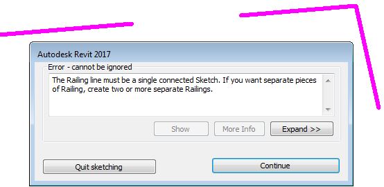
Have you ever tried to create a Revit railing with a split or break in it?  You'd have seen the warning that tells you it is not possible in Revit:

Split Revit Railings

Well, there is a way to do it - yes you can split railings (with lots of provisos, of course).
WARNING: this is another crazy workaround, so use it with caution . . .

In this example, a railing runs through a column, which is not desirable


You may want to break the railing and have a gap either side of the column

The first thing to do is edit the path of the railing, remove the top segments and stop it short of the column by say 50mm.


Once the top part of the railing is removed, Tab-select the 'Top Rail' (or Handrail) - it is important to select one of these sub-elements, not the overall railing.  NB. if your railing does not have either of these sub-elements, this technique won't work (eg. old style top rails)

Once selected, click on 'Edit Rail'

Then click on 'Edit Path' for the Top Rail

This will allow you to add lines to either the top or bottom end of the Top Rail element; but first it is important to set the workplane depending on whether you are adding to the beginning/bottom or end/top.

Select the name of the workplane.   I don't think that either of the 'Pick' options work here.

The workplane will be parallel to the first or last segment of the overall railing - so you'll need to work in either a 3D view or an elevation/section view.  It may be easier to start in 3D so that you can see exactly what you are doing and where.

This command is not explicit about what is going on - in fact Revit is waiting for you to draw some lines, which will become extensions to the Top Rail (or Handrail)

These lines do not need to be directly linked to the ends of the Top Rail - in fact they can be almost anywhere (in the same plane as the end of the Rail).  Start drawing a line the other side of the column from the end of the railing;  at this stage it may be easier to go into a section/elevation view to ensure that it aligns with the railing on the other side of the stair (but keep an eye on the active workplane).

Trace over the other railing (it should snap to it).

Once the Top Rail extension is complete, it will have a gap where the column is.


Be warned:  This is an extension to the Top Rail only - so balusters will not be attached to the underside of the extension.

Supports will not be attached to a Top Rail, so if you require supports on the extension, make sure before you start that your railing has a 'Handrail' sub-element, and add the extension to the Handrail, not to a Top Rail.  If you switch the railing to a type that does not have a Top Rail, the entire extension will disappear (if it was attached to a Top Rail in the first place).  Plan ahead!


Not surprisingly, this workaround is fiddly and not particularly robust - but I am showing it just in case it helps someone out.  In this example, it would probably have been much easier (and safer) to have two separate railings, but it might give people ideas about a use for this technique, so go for it.

Downsides:
  • Only works with a Top Rail or Handrail in the railing
  •  Top Rail and Handrail extensions are not interchangeable
  • Top Rail cannot host supports
  • Will not host balusters or posts beyond the split
  • Will not turn corners in plan
  • Will not automatically adjust heights/angles if the stair changes
  • Is quite confusing for anyone not familiar with railing extensions

Sunday, 22 January 2017

Using Totals in Formulas in Revit Schedules

This has been a frequently asked question on the various forums over the years:
"Is it possible to use a grand total from a schedule in a formula in Revit".  The first response is always No!  Then eventually someone will mention the arcane workaround but it is not always clearly explained so I have decided to show a simple example of what the problem is, and how the workaround might be applied.

I must confess that this is not my original idea - in fact I have found references to the workaround, as far back as 2006 on AUGI by Leonard Raiz (one of the Revit Founders).  More recently (2011), Martijn de Riet published a description of how to calculate a ratio between two area types - this includes the workaround but does a few extra tricks of calculating a ratio of two different sub-totals after first separating them from one grand total, so it is not that easy to understand just the 'totals in formulas' workaround.  Many thanks to Martijn, as I originally learnt the technique from his blog posting.


The Problem With Schedule Totals

Let us suppose that you want to schedule a series of floor areas for a multistorey building and then calculate the ratio between the total of those floor areas against the site area - in Australia we call that the 'Floor Space Ratio'.  There are actually two problems that Revit presents us with here:
  • Revit apparently does not allow you to insert a total of several values into a formula- it only performs the calculations on individual values in each row
  • You can't create a schedule that combines 'Areas' and 'Property Line Areas' because they are different categories - this is another topic so we'll use another quick workaround to deal with that here.
In this example I will use Mass Floor Areas, but they could easily be normal Areas

The Floor Space Ratio calculation is defined as:   'Gross Floor Area' divided by 'Site Area'
It is usually represented as the 'number : 1'   eg. 2.5 : 1

Step 1

  • The first step is to create a Mass Floor schedule, and add the Levels plus Floor Areas
 
  • The first problem we encounter is that you cannot combine a Mass Floor schedule with Site category schedules - so you cannot include the site area value that Revit automatically calculates from your property lines

Workaround 1

  • Create a shared parameter and apply it to the Project Information category
  • This will be a value that you have to type in to the project information page once - and update it if the site area changes, which is obviously a technique prone to user error.  If your site area is not yet settled, and is constantly changing, I would not recommend this method.
  • Once the value is in, you can add the shared parameter to your schedule just by changing the category from the drop-down list and choosing Project Information
 
  • The same value for Site Area will appear in each row, so make sure not to calculate totals for this parameter.
 

Step 2

  • Add a calculated parameter to the schedule, called 'Calc Ratio' (or some such) 
  • Make it a 'Number' type with this formula:
    Floor Area / Site Area
  • Note that each row has its own calculation of the ratio - none of which is correct.
  • If you make the parameter 'Calculate Totals', the Grand Total value of the Ratio will actually be correct - but it makes for a very confusing schedule
  • You could of course collapse the schedule down to one line (untick 'Itemise Every Instance'), and hide the totals - this would display the correct Ratio - but you may require the schedule to show individual floor areas
 
However, there is a way to get Revit to display all the rows of data and to perform calculations on the total value - it requires the following workaround:

Workaround 2

  • In the schedule, add a new calculated parameter called 'F Area Percentage'
  • This time, make it a percentage calculation - click on the 'Percentage' radio button
  • Then select 'Floor Area' as the parameter to calculate 'Of'
  • Leave it to calculate 'By' Grand Total
  • This will list each floor area as a percentage of the total
  • Create another new calculated parameter, called 'Total Floor Area'
  • leave it as a Formula calculation, with type 'Area'
  • Add the Formula:
    Floor Area / F Area Percentage
  • This will give you the correct overall floor area in each row 
  • Be sure not to calculate totals for this parameter.
 
  • Now change the Ratio formula to calculate using the Total Floor Area:
    Total Floor Area / Site Area
  • This will give the correct ratio in each row
  • Remove the Calculate Totals setting for this parameter as the total would be a crazy value

  • You can then hide the two intermediate calculations (Total Floor Area and F Area Percentage) to get a schedule showing the correct site area, floor area and ratio in every row
 

Tidy Up

  • To make the schedule read a little more cleanly, you could sort it by Site Area, with a Header, and then hide the Site Area parameter column - but it only shows the value of the Site Area, not its parameter title, which is not clear enough

  • Then add another Calculated Parameter at the beginning - a text type with a formula:
    "Site Area :"
  • Sort by that parameter before the Site Area, and hide that one too
  • It puts them on two different lines but at least it removes some repetitive information from the body of the schedule
 
 
  • You could try the same with the Floor Space Ratio but unfortunately Revit does not like to sort a schedule by such a formula  - it does not show in the Sort by or Filter list (a bug perhaps? or just a special feature?)
  • You could also put in a few extra text formulas (with blank headings), although they will repeat the same information

Workaround 3

If you can cope with two schedules, it is a lot easier: a simple one liner schedule for the Floor Space ratio calculation, plus a separate schedule list of all the floor areas.
  • You can either create two similar schedules as described above, but collapse one of them down to one line (untick 'Itemise every instance'), and remove the calculations from the full list.
    or
  • Revit makes it simpler to do this operation on Mass Floor areas because you can just create a Mass schedule (as opposed to Mass Floors) that already has a property called 'Gross Floor Area', in which it automatically calculates the total of the Mass Floors - thus you can do a direct calculation on it


I hope this explains the technique clearly.  If you want something more complex, then refer to Martijn de Riet's blog posting on how to calculate a ratio between two area types