BILT Speaker

BILT Speaker
RevitCat - Revit Consultant
Showing posts with label extension. Show all posts

Tuesday, 15 March 2022

Stepped Stair Railing Top Rail Extension in Revit


Following on from an earlier post about stepped railings, here is a bit more information about what happens when you try to add Top Rail extensions.

Weird Railing Stuff - part 18

If the lowest boundary line on the railing path has a Slope property "By Host", the railing segment will be horizontal (assuming you have done a Height Correction on the other segments)

To add an extension to the base of the stair railing:

  • Tab-Select the Top Rail only


  • Edit its Type properties
  • Tick the checkbox for "Plus Tread Depth";  Apply or OK
  • Nothing happens
  • Revit thinks that this segment of the railing is not part of a sloping stair, even though we know it is
  • Edit the Extension Length property to 300mm
  • This time Revit adds the extension (horizontal), as expected (but still no extra tread depth, unlike the straight handrail on the other side of the stair, where it has both)


  •  Confusing huh?

Solution

To solve this, the Slope property of the railing segment must be changed:

  • Select the whole railing
  • Edit the path
  • Select the last segment of the path
  • Change its Slope property to "Sloping"

  • Finish the Path sketch
  • The Top Rail should now be sloping and have both the 300mm extension (horizontal) and the extra tread depth (sloping)

Both railings should now match


Monday, 18 December 2017

Weird Railing Stuff - part 10 - Split railings

[Edit:  Revit 2019 has a new feature that allows you to split a railing - but all it does is to break the selected railing into two separate pieces that no longer relate to each other.  They can then be separately edited.   But just supposing you wanted to have a single railing element that has a gap in it?  Read on . . . .]
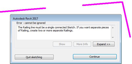
Have you ever tried to create a Revit railing with a split or break in it?  You'd have seen the warning that tells you it is not possible in Revit:

Split Revit Railings

Well, there is a way to do it - yes you can split railings (with lots of provisos, of course).
WARNING: this is another crazy workaround, so use it with caution . . .

In this example, a railing runs through a column, which is not desirable


You may want to break the railing and have a gap either side of the column

The first thing to do is edit the path of the railing, remove the top segments and stop it short of the column by say 50mm.


Once the top part of the railing is removed, Tab-select the 'Top Rail' (or Handrail) - it is important to select one of these sub-elements, not the overall railing.  NB. if your railing does not have either of these sub-elements, this technique won't work (eg. old style top rails)

Once selected, click on 'Edit Rail'

Then click on 'Edit Path' for the Top Rail

This will allow you to add lines to either the top or bottom end of the Top Rail element; but first it is important to set the workplane depending on whether you are adding to the beginning/bottom or end/top.

Select the name of the workplane.   I don't think that either of the 'Pick' options work here.

The workplane will be parallel to the first or last segment of the overall railing - so you'll need to work in either a 3D view or an elevation/section view.  It may be easier to start in 3D so that you can see exactly what you are doing and where.

This command is not explicit about what is going on - in fact Revit is waiting for you to draw some lines, which will become extensions to the Top Rail (or Handrail)

These lines do not need to be directly linked to the ends of the Top Rail - in fact they can be almost anywhere (in the same plane as the end of the Rail).  Start drawing a line the other side of the column from the end of the railing;  at this stage it may be easier to go into a section/elevation view to ensure that it aligns with the railing on the other side of the stair (but keep an eye on the active workplane).

Trace over the other railing (it should snap to it).

Once the Top Rail extension is complete, it will have a gap where the column is.


Be warned:  This is an extension to the Top Rail only - so balusters will not be attached to the underside of the extension.

Supports will not be attached to a Top Rail, so if you require supports on the extension, make sure before you start that your railing has a 'Handrail' sub-element, and add the extension to the Handrail, not to a Top Rail.  If you switch the railing to a type that does not have a Top Rail, the entire extension will disappear (if it was attached to a Top Rail in the first place).  Plan ahead!


Not surprisingly, this workaround is fiddly and not particularly robust - but I am showing it just in case it helps someone out.  In this example, it would probably have been much easier (and safer) to have two separate railings, but it might give people ideas about a use for this technique, so go for it.

Downsides:
  • Only works with a Top Rail or Handrail in the railing
  •  Top Rail and Handrail extensions are not interchangeable
  • Top Rail cannot host supports
  • Will not host balusters or posts beyond the split
  • Will not turn corners in plan
  • Will not automatically adjust heights/angles if the stair changes
  • Is quite confusing for anyone not familiar with railing extensions

Wednesday, 27 September 2017

Weird Railing Stuff - part 7a - Support Spacing Postscript

I mentioned in my previous post about handrail support spacing that the distance between supports is measured along the length of the handrail regardless of its angle, rather than a horizontal plan distance (which is used by other railing element spacing).  It turns out that it gets even weirder:

Revit Railings Get Weirder and Weirder

I thought I would check where it is measured on the handrail, and whether it takes into account a fillet radius if you have one.
  • On a horizontal railing, it measures support spacing on the underside of the handrail
  • On a sloping railing, the supports seem to be attached to the handrail a bit higher - you can snap to the top endpoint of the support.  In the example I tested, with a 75mm high support, the top is about 7mm vertically into the handrail.
  • This means that the spacing is measured slightly above the underside of a sloping handrail - this may vary depending on the angle and the type of support.  However, I have no desire to investigate any further - this is weird enough already.
  • If you have a curved transition from horizontal to sloping handrail (fillet radius), the support spacing measurement transitions (on a radius) from underside of handrail to somewhere above the underside.
  • This means that you cannot accurately predict where the supports will end up - unless you do a checking diagram like the one below.  I can tell you, this is the first and last one I will ever do!

 Extension to Floor

I know that you'd never put supports like this on a handrail with a vertical extension to the floor, but I just wanted to see what it does with the spacing:

The answer is that the supports get flipped to the outside of the handrail (what becomes the top when it turns the corner to be horizontal).  However, the spacing between the two supports as it goes from vertical to horizontal is not predictable.  In the example above, the typical spacing is 200mm (just to be certain it doesn't come away from the wall!), but the distance measured orthogonally between those two supports on the corner is only about 190mm - so we are adrift by 10mm.  As I said, it is not easy to predict exactly where the supports will end up.

If we had a start/end indent property, we could at least make a guess, then tweak the indent value until it is exactly where we want the first/last support - without having to unpin the supports (which has its own problems, to be discussed later).  Please go to the official Revit Ideas website and vote up my idea on this

Just to entertain you, here is what Revit does when you have a handrail extension to a wall - note that the support goes to the top of the handrail again (not that you actually want a support when the handrail fixes to a wall, of course!).

More on this subject:

Friday, 24 April 2015

Weird Revit Railing Stuff - part 5 - Extensions / Terminations


In my previous post I described how top rail / handrail terminations in Revit are not visible in plan, thus rendering them useless for 2d documentation.  They have another 'feature' that makes them unreliable for use in any model:

Unreliable Rail Extension Length

When you first define a new railing type, with a top rail that has a termination and extensions, the termination goes outside the length of the extensions:
If you then change the railing for some other railing type, and then change it back to the original type (with extension + termination), the termination is now within the extension length - meaning that the whole railing length gets shorter.

Of course you can't see the extensions (unless you select the railings) - but the rail just looks shorter.

This has been acknowledged by Autodesk as a bug, so no doubt it will be fixed in due course.  Let us hope that they also fix the visibility issue, which is not yet acknowledged as a bug - last I heard it was "As Designed".

Possible Workaround

If you really want to use terminations, and don't mind about the plan visibility issue, there is a workaround to the extension length issue:
  • Go to a section view and select the top rail
 
  • Make sure you get the top rail by Tab-Select, otherwise you'll get the whole railing
 
  • Click on Edit Rail in the ribbon
  • The extension line will show blue, but note that the termnation has already moved
 
  • Edit Path (note the Edit Rail Path is different from normal Edit Path)
  • The extension sketch lines are now editable - drag the extension sketch line to exactly where you want it

  • When you finish editing, the termination will be where you want it to be, and will not move without your permission
The main problem with this workaround is that you have to edit every single instance of the extension/termination.  The other option might be to just make the extension longer than required (by the termination length), and live with the fact that Revit will shorten it - of course you need to swap the type to make it do so.

Organic Railings

  • While you are editing the extension path, you could have a bit of fun, and curve the extension line.  Antonio Gaudi would be proud of you

  • Or you could go really crazy

  • But even Gaudi wouldn't like this result as his designs were always very considered even when looking arbitrary


Railing designed by Antonio Gaudi, Barcelona


Dimensioning Terminations

Another issue:
You cannot dimension terminations in section (or plan, obviously), which is a limitation for serious documentation.
Perhaps you could create a detail view and place a separate termination component that is invisible in all other views?   Another nasty workaround - but what else can we do?


Monday, 20 April 2015

Weird Revit Railing Stuff - part 4 - Handrail Terminations


Staircase on Kukulkan Temple at Chichen Itza, Mexico

Railing Termination Visibility

The great temples at Chichen Itza (Mexico) were built well over a thousand years ago.  The Mayan/Toltec architects and engineers who designed them created some grand staircases.  They didn't have the same building regulations and OH&S concerns that we have today, so their concepts of railings and balustrades was a bit different.  However, they did love to put grand terminations at the base of their balustrades - in this case, representations of Kukulkan, the feathered serpent deity:
Kukulkan Serpent balustrade terminations

Of course they didn't use CAD, let alone BIM to help them design the stairs - they were brilliant mathematicians, who probably worked it all out in their heads.  The angles of the stairs were not designed to make it easy to climb up or down them - it was more about astronomical significance and perfect acoustics so that massed crowds at the base could hear the leaders speaking from the top of the stairs.  The Toltecs also practised human sacrifice of a rather gruesome nature.

At around the same time on the other side of the world, another culture was also creating impressive architecture with similarly steep staircases - at Angkor Wat in the Khmer Empire (now Cambodia).  They went in for some pretty substantial stone railings, with elaborate terminations in the form of seven-headed serpents (Nagas).

Angkor Wat railing terminations
What has all this to do with Revit?  Well, in version 2013 a new feature was added to the railing functionality:  Top/Hand rail 'terminations'.  The developers probably did not have in mind representations of serpents heads - but there are plenty of modern day uses.


Revit Railing Terminations

First a quick description of how to create rail terminations in Revit, as it is very convoluted.
Step 1 - Termination Family
  • First you have to create a termination family from the '(Metric or Imperial) Railing Termination' template.  This has an inbuilt 'Extension Length' parameter.
  • Once loaded into a project, this family has a category of 'Terminations' and could be placed on its own (but you would not normally do so).  In the family browser it is listed as a subcategory of Railings (with whatever name you give it).
Step 2 - Adding a termination to a Railing 
  • Terminations cannot be added directly to railings - you have to define them as part of either a 'Top Rail' or 'Handrail' (both new features in v2013);  these can then be selected as part of a railing.  So, they can only be used if your railing has one of these new features.
Top rail type properties
Railing type properties
  • The termination will be added to the end of the top rail (or handrail), perpendicular to the rail.  Normally it will be on the end of the rail but some strange behaviour can go on there - to be described later.

  • Terminations can be used in combination with 'Extensions' - another new feature in v2013, which are a property of Top Rails and Handrails.
 
  • You can add an extra tread length at the base of the stair, which maintains the railing slope
  • You can also add a further extension length, which would typically be horizontal if you already added the extra tread
Extra tread plus 300mm extension as per Australian BCA

  • The 3D view of the railing will display whatever you have modelled - my ambitions for scaring people were quite modest compared with the Mayans/Toltecs/Khmers, but might be appropriate for renovating a Gothic mansion or the bat-cave.

Rail Termination Visibility

Within the family editor,  you have typical controls as expected:
  • Revit will not allow you to create subcategories, which is to be expected, as the termination is itself a subcategory.
  • None of the family Category settings make any difference to the behaviour of the family in the project, except the category itself

  • Rail terminations have standard Revit visibility settings (Plan, Front, Left; coarse, medium, fine) for selected 3d forms within the family.

The problems start once you get into the project environment:
  • Rail Terminations are visible in 3D, section and elevation - but terminations are not visible in plan.  It makes no difference what view settings you use, they are just plain invisible.
 
  •  If you hover the cursor over the railing, you can see the termination there
  •  Select the railing, and there it is, plain as day, but it disappears as soon as you deselect the railing
This is a bug that has been in the software since Terminations were introduced in v2013.  It has been reported to Autodesk by various people and documented elsewhere (18 months ago).  There are several references to this in various forums, but they remain unanswered by Autodesk.

Terminations Terminated

The upshot of this bug is that Terminations are effectively useless to us if we want to document anything in plan.  The industry has not yet achieved the goal of supplying 3D models for final information to contractors, so we still rely on 2d documentation.
There is another bug to do with extensions and terminations in combination, which does not help matters either.
It is technically possible to use newel posts (balusters) to achieve this end, but they have all sorts of other issues - not the least of which is the difficulty of keeping them on the end of the rail, at the correct angle.

What would the ancients have done?  Well, they probably managed to build their serpent terminations without 2D plans, but they would not have been impressed by the lack of attention to detail shown by modern day software developers.  The Mayans and Khmers might have let them off with just a severe scolding.  But I'm not so sure about the Toltecs?  Did I mention that they introduced human sacrifice?

Antonio Gaudi probably would not have been very impressed either.
Staircase termination by Antonio Gaudi, Barcelona

Naga handrail terminations - Wat Hanchey, Cambodia

More about top rails:
Top Rail Properties in Revit Railings
Weird Stuff in Railings - part 1 - Top Rail Transitions
Weird Stuff in Railings - part 2 - Railing Extents
Weird Stuff in Railings - part 3 - Rail Offsets 
Weird Stuff in Railings - part 5 - Rail Extension Length