BILT Speaker

BILT Speaker
RevitCat - Revit Consultant
Showing posts with label sketch. Show all posts

Saturday, 26 February 2022

Poor Man's Array in Revit

There are several situations in Revit where the Array tool is not available - one of those is when using the Sketch commands.  Here is a quick workaround.

Stair Sketch Example

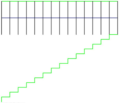
In this example I wanted to create a stepped side to a stair in the sketch mode.


When I selected two of the stepped boundary lines, I discovered to my horror that the Array tool is greyed out.

Workaround

Instead of using the Array tool, use the Copy tool, making sure that the 'Multiple' setting is ticked on the Options Bar

Revit first asks for the Start Point

Make sure to snap to the first end point of one of the items being copied

Then snap to the second end point

Then snap to the third end point - being the end of the first copy

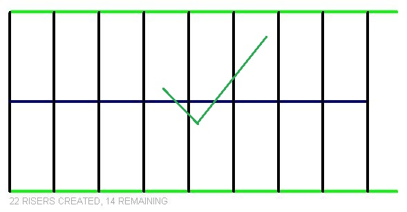
Keep snapping to the end of the most recent copy until you have created your array - it is pretty quick once you get going.

In this example I had to delete the last created line

If you need a lot of copies - say 100, you have two choices:

  • Concentrate hard and try not to fall asleep
    or
  • Make 20 copies then stop and select all 20 steps;  copy those 5 times

Array Done!

I figured this trick out many years ago, and I needed it to achieve the stepped side to a stair sketch for another blog post - so I thought I'd document it in case it helps someone out there.

This might get you thinking about other uses of this simple technique.

I tried it for radial arrays, for which you would need to use the Rotate tool - but unfortunately that tool does not allow multiple copies.


Monday, 1 April 2019

Stepped Steps in Revit Stairs


I had a question recently about how to create a Revit stair that is stepped in plan?  It is actually not that hard to do but the method is not so intuitive - so here are some instructions:

Tapered Stair

For the record, we'll start with a tapered stair, to get the methodology - as that is very easy:
  • Create a stair with a straight run
 
  • Select the run (in stair edit mode)
  •  Convert the run to a sketch 
 
  • Select the run and 'Edit Sketch'
 
  • Adjust the angle of one or both sides
 
  • No need to trim the riser lines (providing the boundary lines up with the end risers
  • Finish the sketch and the stair


Stepped Stair

Follow a similar process as the tapered stair to start with:

  • Create a stair with a straight run
 
  • Select the run (in stair edit mode)
  • Convert the run to a sketch - this stage is not reversible, so you need to be sure about it
 
  • Select the run and 'Edit Sketch'
  • The sides and back of each step need to be drawn as 'Boundary Lines', which show green in the sketch mode [Refer to Poor Man's Array for a tip on how to do this]
  • As per the tapered stair, the riser lines do not need to extend out to the boundary lines - this makes it easier to sketch and to modify later
 
  • Finish the sketch and the stair


You may get some interesting results with the railings, but that can be dealt with in the next blog post . . . . Stepped Handrails in Revit


Saturday, 26 January 2019

How Do You Solve a Problem Like Ma Railings?


Have you ever encountered a problem with out-of-control railings in Revit?  OK, so maybe the structure shown above is not a haywire railing, and was meant to be like that, but most Revit users have struggled with trying to model railings as they should be.

How Do You Solve a Problem Like Ma Railings (in Revit)?  *


* with apologies to Richard Rodgers for misappropriating his song title (How Do You Solve a Problem Like Maria? from the Sound of Music, By Rodgers and Hammerstein) - not to be confused with Richard Rogers (no d), the architect who designed many famous buildings, such as the Pompidou Centre in Paris (with Renzo Piano) and the Lloyds Building in London.

Richard Rogers surely did not struggle with trying to model railings in Revit, as those buildings were designed long before the advent of such software.  These days we certainly do struggle with the software - Revit has been around for almost 20 years and it still it does not enable us to model Railings the way we want them (except for the most simple handrail).  There are many problems with the railing tool in Revit, some of which have been documented on this blog - see the list below.  Over the years, we have benefitted from several minor improvements to the railing tool - for which we are very grateful.  However, there is one fundamental problem that has not been resolved - and that is the inability to control the location of individual balusters.

Baluster Placement - a Fundamental Flaw

The railing sample file shows some relatively complex looking examples - but these are just straight runs on the level.  As soon as you try to use them on stairs, things start going wrong with the baluster placement.

This example is done using two alternating balusters - one is just a post, while the other is glass with fixings.  The glass baluster is very good at adjusting the angle of its top and base (if you create the family properly). 
 
When it comes to spacing, it is pretty hopeless:  you get gaps whenever there is a break in the pattern.
Standard railing with glass balusters
There are some limited controls within the baluster placement type properties, but no single combination of settings will ever work on the whole stair railing.

Spreading the pattern to fit does resolve some issues, sometimes. . . .

Changing the 'Break-Pattern' property to 'Never' can have some weird results

Reverting the pattern to 'Centred' does not fix it either - you may end up with panels across a change in angle, where the panel is not trimmed properly.

Workarounds

There are a number of ways that people get around these problems, but none of them is satisfactory:

1.  You can try using 'Handrail Supports' to represent balusters, but that has at least two problems:
  • Handrail supports do not respond to changes in angle of the stair, so you need to build that in as a user control that has to be manually set every time
  • Handrail supports can be unpinned and then moved (or changed to another type), but the moving process is very tricky - see Moving Handrail Supports
    It is also possible to very easily lose the positions by accidentally resetting the railing.
2.  Model the glass as a continuous rail element, use balusters and/or handrail supports to represent the fixings and vertical joints in the glass.  More on that another time.

3.  Model the railing 'in-place'.  This is a really bad idea as it screws up the subcategories, visibility etc;  And worse still, it does not update when the stair changes

4.  Just model a Top Rail / Handrail (with no balusters), which shows up in plan.  Document the railing in 2D as drafting views or as detail elements on stair sections.  This is a terrible solution (very un-Revit-like), but it can save huge amounts of modelling time - so it is done quite commonly in the industry.  Of course, it can lead to errors on site . . . .

Railing Fixes

If we had the ability to control the baluster placement in much the same way that curtain walls operate, it would help resolve this fundamental flaw in the railing tool;  this would require the ability to include variable width panels too.  Of course there need to be many other minor fixes in addition to that. 

On the Autodesk Revit Roadmap, Railings were flagged as 'fixed', a couple of years ago, on the basis of a number of minor enhancements.  Clearly it is nowhere near being fixed - see this request on 'Revit Ideas'  Railing Overhaul - Resolution of Limitations - from Chris Price (Mr Spot).

Weird Railing Stuff Blogs

Over the last few years I have posted many blog articles on the many weird quirks of using Revit to model Railings.  Some articles just document the inconsistencies and strange behaviour - just so you know what is going on; other articles offer some workarounds and ground-rules that might help you along:

Revit Railing Enhancement Requests

Autodesk  have a 'Revit Ideas' website that allows you to vote for enhancement requests.  I have compiled a list of stair/railing related ideas - please, all of you vote for some of these requests - if you don't vote, Autodesk will continue to consider them as fixed.

Monday, 18 January 2016

Revit Stair Component Sketch Tool Rules

Last month I posted opinions about the pros and cons of doing sketched stairs using the old tools or the new Component Sketch tools.  Now we are going to look at some of the detailed differences between the two methods:


Stair by Sketch

As I mentioned last time, when you first start a 'Stair by Sketch', it seems to be more efficient because you only need to click start and end of a run and it places all the lines for risers, boundaries and run.  From that moment on, you will start losing time to the component sketch method, as you discover how unforgiving the old sketch tool is - one tiny infringement of the rules and it will not complete the sketch.  Most likely you will spend hours trying to resolve it.
Old sketch tool - 2 click run creation

Stair by Component Sketch


When you start the component sketch tool, it does not draw any lines for you - which is why I recommend using the Run tool then converting the run to a sketch.  Once you have a component sketch, Revit is more forgiving about how you complete the line work and finish the sketch.  Revit also gives you better warning messages when the sketch is not good enough.  The rules are a little mysterious, but I have tried to learn them by seeing what I could get away with or not - so here are some of the examples:

Stair Path Lines

The stair path lines define the plan extent of the risers -  they also define exactly where the stair path arrow will go.  On stair Runs they have to be very precise, as the error message will tell you:
"Invalid stair path. Stair path should connect both start and end riser, and cross all other risers."
  • The Stair Path line must start on the first riser 
  • The Stair Path line must finish on the last riser
  • The Stair Path line cannot stop short or go past the riser lines
 
 
  • Two intersecting run lines must meet perfectly at a corner on a cranked or winder run (not cross over each other)
 
  • Landings also have a Stair Path line, but its only purpose is to locate the stair path arrow will go.  For the penalty of no longer having an automatic landing, you could convert it to a sketch in order to get your stair paths right.
Edit landing to create T-shaped stair path
  • In fact you can pretty much do what you like with them on a sketched landing.


Boundary Lines

Boundary lines define the edges of a stair run.
  • Boundary lines are actually displayed dark blue, but you have to zoom in really, really close to see that they are not black lines.
  • They must extend up to or beyond the last/first risers, but not stop short
Boundary line overruns OK
  
Boundary line shortfalls will not work

  • They do not have to join with the last/first riser, as long as they line up with the end - there can be a gap as Revit treats the riser lines as infinite (or at least very long)
Risers do not need to join boundary lines
Risers can overlap boundary lines
Stair run created from previous sketch
  • Two boundary lines meeting at a corner must intersect (cannot have a gap or overlap)
 
  •  Stair boundaries can be curved
Curved stair boundaries
Maybe not such a good design
In the above example it would be better if the curved lines were riser lines not boundaries

Riser Lines

It is not possible to change lines from boundary to riser (or vice versa), so you need to choose the correct line type before drawing them.
Curved riser lines
  •  Riser lines can meet at a corner, but not overlap


Warning Messages

Be sure to read exactly what the warning says.
  • If it says 'Invalid Sketch.  Can't create run from this sketch' then it is a problem with the sketch (not surprisingly)
  • If it says 'Invalid stair path' don't waste time looking at the boundary or riser lines - just check the stair path lines (you know, the blue ones!)
  • If it says 'Cannot make stair' - then it is not a sketch problem, but most likely a 3D geometry problem - maybe an impossibly thin riser element (in which case try changing it to a monolithic stair just to check).

What Can You Get Away With?

Could this possibly work as a stair sketch?

With the component sketch tool, no problem

Link to Stair Sketch Tool

Link to Stair Index Page