BILT Speaker

BILT Speaker
RevitCat - Revit Consultant
Showing posts with label riser. Show all posts

Monday, 1 April 2019

Stepped Steps in Revit Stairs


I had a question recently about how to create a Revit stair that is stepped in plan?  It is actually not that hard to do but the method is not so intuitive - so here are some instructions:

Tapered Stair

For the record, we'll start with a tapered stair, to get the methodology - as that is very easy:
  • Create a stair with a straight run
 
  • Select the run (in stair edit mode)
  •  Convert the run to a sketch 
 
  • Select the run and 'Edit Sketch'
 
  • Adjust the angle of one or both sides
 
  • No need to trim the riser lines (providing the boundary lines up with the end risers
  • Finish the sketch and the stair


Stepped Stair

Follow a similar process as the tapered stair to start with:

  • Create a stair with a straight run
 
  • Select the run (in stair edit mode)
  • Convert the run to a sketch - this stage is not reversible, so you need to be sure about it
 
  • Select the run and 'Edit Sketch'
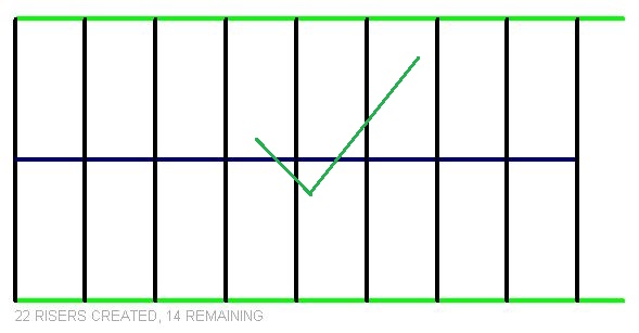
  • The sides and back of each step need to be drawn as 'Boundary Lines', which show green in the sketch mode [Refer to Poor Man's Array for a tip on how to do this]
  • As per the tapered stair, the riser lines do not need to extend out to the boundary lines - this makes it easier to sketch and to modify later
 
  • Finish the sketch and the stair


You may get some interesting results with the railings, but that can be dealt with in the next blog post . . . . Stepped Handrails in Revit


Friday, 1 April 2016

Revit Stair Subcategories and Materials

Last year I posted a detailed description of what the 'new' stair component subcategories do in different views - plan vs section.
It seems that I missed something - Dan Stine (author of several Revit text books) has pointed out that the Treads/Risers subcategory does actually have an effect in plan views:
It controls the materials and surface patterns of the treads.  I did some testing to understand the subtleties of how this works. . . . .

Here I am using my subcategory visibility colour overrides to make it easier to see what is being controlled by which subcategory.

 Normally turning the 'Treads/Risers' subcategory seems to have no effect in a plan view.
This would be the case for one of two reasons:
  • If your monolithic stair run does not have a separate tread
 
  • If the stair run does have a tread, but the tread material does not have any surface pattern
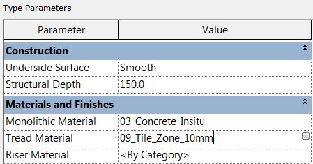
Tread material - Run type property
 
Material properties of stair run tread

However, if the material of the tread is changed so that it has a surface pattern, this will display in a plan view

It looks different depending on the visual style of the view:
Hidden Line View with tiles on treads
Shaded View with tiles on treads
Realistic View with tiles on treads

If you then hide the Treads/Risers subcategory, the tread material will no longer be displayed.  Instead it will display the material of the underlying stair structure - if it is monolithic, that would most likely be concrete.

We normally do not have a surface pattern on concrete because it would show up in too many views.  However, if you do have a surface pattern, it will show once you have hidden the treads


Hidden Line - concrete surface pattern
Shaded View - concrete surface pattern
Realistic View - monolithic concrete stair


Really Weird Stair Stuff

In order to hide the surface pattern of the underlying monolithic material in a plan view, you have to turn off both 'Nosing Line' & 'Riser Lines' subcategories.  Turn off just one or other of them and you hide the lines, but not the material surface pattern.  That makes no sense to me.
Plan subcategories for materials


 How do you hide the material of the underlying monolithic structure?
  1. Make sure the material does not have a surface pattern, and view it in Hidden Line or Shaded View.  Or:
  2. Turn off the 'Nosing Line' and 'Riser Lines' subcategories.  That could be frustrating if you need to see the nosing or riser lines themselves!  
    Or (the better solution):
  3. Go to the Surface Pattern override for the whole stair;  untick the Pattern Overrides 'Visible' checkbox (won't work in a realistic view)
        The Pattern will then list as 'Hidden'


Which one of the three solutions you choose depends on exactly the result you are after, and on what Visual Style setting you have for the view.

For a Realistic View, you can hide the tread material (by Tread/Riser subcategory) but cannot hide the underlying monolithic material at all.

Material Linestyle Overrides 

Unlike the actual linework of the stairs, the lines within the surface patterns cannot have their weight or linestyle overridden in the Visibility Graphics dialog - they follow the standard rules for hatching lines.  The colour can be overridden, but you have to change the overall stair category pattern colour override, not the subcategory line colour override.  This means that the button to click on for colour override is quite different to the location of the 'Treads/Risers' subcategory visibility control checkbox(es).


The actual hatching pattern can be overridden from the same dialog - this allows you to choose a totally different pattern just for that view.  If you set it to "No Pattern", it just clears the override, rather than temporarily removing the pattern as an override - which is frustrating if that was the result that you wanted, particularly if you just tried to override one element, not all in that view.

The line weight of the surface patterns cannot be overridden by view, but that is another story . . . .

Monday, 18 January 2016

Revit Stair Component Sketch Tool Rules

Last month I posted opinions about the pros and cons of doing sketched stairs using the old tools or the new Component Sketch tools.  Now we are going to look at some of the detailed differences between the two methods:


Stair by Sketch

As I mentioned last time, when you first start a 'Stair by Sketch', it seems to be more efficient because you only need to click start and end of a run and it places all the lines for risers, boundaries and run.  From that moment on, you will start losing time to the component sketch method, as you discover how unforgiving the old sketch tool is - one tiny infringement of the rules and it will not complete the sketch.  Most likely you will spend hours trying to resolve it.
Old sketch tool - 2 click run creation

Stair by Component Sketch


When you start the component sketch tool, it does not draw any lines for you - which is why I recommend using the Run tool then converting the run to a sketch.  Once you have a component sketch, Revit is more forgiving about how you complete the line work and finish the sketch.  Revit also gives you better warning messages when the sketch is not good enough.  The rules are a little mysterious, but I have tried to learn them by seeing what I could get away with or not - so here are some of the examples:

Stair Path Lines

The stair path lines define the plan extent of the risers -  they also define exactly where the stair path arrow will go.  On stair Runs they have to be very precise, as the error message will tell you:
"Invalid stair path. Stair path should connect both start and end riser, and cross all other risers."
  • The Stair Path line must start on the first riser 
  • The Stair Path line must finish on the last riser
  • The Stair Path line cannot stop short or go past the riser lines
 
 
  • Two intersecting run lines must meet perfectly at a corner on a cranked or winder run (not cross over each other)
 
  • Landings also have a Stair Path line, but its only purpose is to locate the stair path arrow will go.  For the penalty of no longer having an automatic landing, you could convert it to a sketch in order to get your stair paths right.
Edit landing to create T-shaped stair path
  • In fact you can pretty much do what you like with them on a sketched landing.


Boundary Lines

Boundary lines define the edges of a stair run.
  • Boundary lines are actually displayed dark blue, but you have to zoom in really, really close to see that they are not black lines.
  • They must extend up to or beyond the last/first risers, but not stop short
Boundary line overruns OK
  
Boundary line shortfalls will not work

  • They do not have to join with the last/first riser, as long as they line up with the end - there can be a gap as Revit treats the riser lines as infinite (or at least very long)
Risers do not need to join boundary lines
Risers can overlap boundary lines
Stair run created from previous sketch
  • Two boundary lines meeting at a corner must intersect (cannot have a gap or overlap)
 
  •  Stair boundaries can be curved
Curved stair boundaries
Maybe not such a good design
In the above example it would be better if the curved lines were riser lines not boundaries

Riser Lines

It is not possible to change lines from boundary to riser (or vice versa), so you need to choose the correct line type before drawing them.
Curved riser lines
  •  Riser lines can meet at a corner, but not overlap


Warning Messages

Be sure to read exactly what the warning says.
  • If it says 'Invalid Sketch.  Can't create run from this sketch' then it is a problem with the sketch (not surprisingly)
  • If it says 'Invalid stair path' don't waste time looking at the boundary or riser lines - just check the stair path lines (you know, the blue ones!)
  • If it says 'Cannot make stair' - then it is not a sketch problem, but most likely a 3D geometry problem - maybe an impossibly thin riser element (in which case try changing it to a monolithic stair just to check).

What Can You Get Away With?

Could this possibly work as a stair sketch?

With the component sketch tool, no problem

Link to Stair Sketch Tool

Link to Stair Index Page