BILT Speaker

BILT Speaker
RevitCat - Revit Consultant
Showing posts with label railing. Show all posts

Tuesday, 15 March 2022

Stepped Stair Railing Top Rail Extension in Revit


Following on from an earlier post about stepped railings, here is a bit more information about what happens when you try to add Top Rail extensions.

Weird Railing Stuff - part 18

If the lowest boundary line on the railing path has a Slope property "By Host", the railing segment will be horizontal (assuming you have done a Height Correction on the other segments)

To add an extension to the base of the stair railing:

  • Tab-Select the Top Rail only


  • Edit its Type properties
  • Tick the checkbox for "Plus Tread Depth";  Apply or OK
  • Nothing happens
  • Revit thinks that this segment of the railing is not part of a sloping stair, even though we know it is
  • Edit the Extension Length property to 300mm
  • This time Revit adds the extension (horizontal), as expected (but still no extra tread depth, unlike the straight handrail on the other side of the stair, where it has both)


  •  Confusing huh?

Solution

To solve this, the Slope property of the railing segment must be changed:

  • Select the whole railing
  • Edit the path
  • Select the last segment of the path
  • Change its Slope property to "Sloping"

  • Finish the Path sketch
  • The Top Rail should now be sloping and have both the 300mm extension (horizontal) and the extra tread depth (sloping)

Both railings should now match


Tuesday, 8 February 2022

Stepped Handrail on Stepped Stairs in Revit

A couple of years back I posted on how to create a stair with stepped sides. 


I always intended to follow it up with what happens to the handrail, and how to solve it?  Well, it is never too late.


Just in case you are wondering how to create the stepped side to the stair run in sketch mode - here is a trick for creating a DIY array in Revit.


When you create a stepped boundary for a stair run, the handrail also becomes stepped, but it is pretty clunky.


Baluster Placement

The first thing to notice is the hideous baluster placement - it is placing one at each change of direction, and one (or more) in the middle of each segment.

To tidy it up:

  • we will probably have to create a new railing type (to avoid messing up the straight railing on the other side of the stair
  • then edit the railing type properties; and the baluster placement
  • Untick the checkbox for 'Use baluster per tread on stairs'


  •  Balusters will only be placed at ends of each segment

Alternatively you could try the opposite: keep the Baluster per tread, but remove the start and end balusters - but then you lose control of the baluster locations in the segments running parallel to treads (not centred).


Top Rail Properties

You may not like the clunky Art Deco look of the vertical "Gooseneck" handrail segments, so the first step is to tab-select just the top rail (not the whole handrail) - then look at its Type properties

  • Change the Transitions from 'Gooseneck' to 'Simple' (or None)
  • Revit will give a not very helpful "not continuous rail" warning:
  • Whichever you choose (Simple or None), you get 'None', as Revit has a headache and thinks it is all too difficult, so it simply can't be bothered to join the segments

Edit Railing Segments

The next thing to try is editing the whole railing path:

  • Select the handrail
  • Edit the path

  • Select the first path segment at the base of the stair
  • Check its properties, displayed on the Option Bar
  • Change the Slope from 'By Host' to 'Sloped'

  • Finish the Sketch
  • Nothing appears to happen to the railing slope!  We will solve that later.
  • Edit the path again
  • Select the next segment that should be sloping (3rd from end)
  • Change its Slope to 'Sloped'
 
This is getting tedious, so let us try a couple of shortcut:

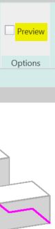
  • Instead of finishing the sketch to see how it looks, you could try the cool new Railing "Preview" feature in the ribbon menu (in a 3D view)


  • Tick the Preview checkbox
  • Aaaargh - it does not work when you adjust railing segment properties! It does not show the adjusted slope property.  You still have to Finish the sketch to see the effect


  •  Edit the path again
  • Select several segments to change their Slope property
  • Aaargh - the properties are not shown on the Option Bar when you select multiple segments!
  • Change the Slope properties for every alternate segment - one by one!
  • Finish the Path sketch

Something is wrong with the overall height of the railing when compared to the straight railing on the other side of the stair.  

  • This can be checked in an elevation view

Height Correction

To solve this, one way is to change the Height Correction property of each segment:
  • Edit the railing path again
  • Select the first segment
  • Change its Height Correction property to Custom; with a value to match the riser height
  • Finish the Path sketch
  • The railing height is now correct (more or less)
  • The lowest segment is now sloping

  • Check it in elevation


Now who has a headache?  Not just Revit!

This is a crazy amount of work to do in order to get this sort of correct.

Of course, you could avoid all this by just putting in a straight diagonal railing, but the point of this blog is to demonstrate the problems with stairs and railings - and to show workarounds (however nasty they may be).   There may also be situations where the diagonal railing is not appropriate - perhaps where the stepped sides are much larger steps.


Thursday, 1 April 2021

Rustic Railings in Revit

There has been a lot of talk over the years about just how hard the Revit stair and railing tools are to work with.

I decided to do an experiment - and see how long it took to build an actual stair and railing vs building the same thing in Revit.

I chose to build a rustic-style stair as it was outdoors in a wild garden setting.

Rustic Stair and Railing Hackathon

I thought I had better give Revit a fighting chance by not zeroing in on one of Revit's biggest railing weaknesses:  "Baluster Spacing"

  • So I decided not to include any balusters at all.  

Technical Details

  • The stairs were made from hand-hewn sandstone, with irregular shapes and slightly differing tread widths;  riser heights were near enough the same for each step.  Stones were carved to exact size and placed without mortar - exactly how the ancient Egyptians, Mayans, Aztecs et al worked their stone structures.
  • Railing was made from locally sourced Melaleuca timber - hand-cut on site:  Two posts and one 'Top Rail', all sourced from the same tree.  The top post and handrail were left to cure in the open for several weeks;  the lower post was cut and installed the next day.
  • The handrail was fixed to the posts with tuppenny nails.
  • Real stairs and railings were built without any drawings - I couldn't wait for those to be finished.
  • The virtual stairs/railings were created using the "New" stair tools (post Revit 2013) & the "Old" railing tools (circa v2 with minor improvements in v2013)

Finished Product

The finished stair and railing

Unfortunately I don't have an image from Revit, because it was created in a later version that I could not open with my current version of Revit.

The Stats

  • The real stair took approximately 18 months, done a few hours at a time at weekends.
  • The real handrail was build about a year later - it took approximately 2 months, again done at weekends.
  • The virtual stair took 5.5 years, including waiting time between Revit versions - hoping that problems encountered had been fixed in the next version.
  • The virtual railing is still unfinished, awaiting software improvements.

Problems Encountered

  • The lower railing post was obviously installed too quickly after cutting, as it started to sprout a few weeks later (inadequate curing time).
  • I really struggled with applying the virtual stair hand-cut stone materials to the treads, especially in 2D plans.
  • Without any balusters on the virtual railing, the 'Building Inspector' would not give approval to the railing.

The Winner

Hands down winner was the real stair/railing:

  • It was so much easier and quicker to build the real thing than attempting a virtual model.
  • It was very therapeutic working manually on the stone and timber at weekends after a hard week of Reviteering.
  • It was ever so slightly less therapeutic grappling with the virtual tools for stairs and railings in Revit.


1st April 2021 (Australia).


Saturday, 26 January 2019

How Do You Solve a Problem Like Ma Railings?


Have you ever encountered a problem with out-of-control railings in Revit?  OK, so maybe the structure shown above is not a haywire railing, and was meant to be like that, but most Revit users have struggled with trying to model railings as they should be.

How Do You Solve a Problem Like Ma Railings (in Revit)?  *


* with apologies to Richard Rodgers for misappropriating his song title (How Do You Solve a Problem Like Maria? from the Sound of Music, By Rodgers and Hammerstein) - not to be confused with Richard Rogers (no d), the architect who designed many famous buildings, such as the Pompidou Centre in Paris (with Renzo Piano) and the Lloyds Building in London.

Richard Rogers surely did not struggle with trying to model railings in Revit, as those buildings were designed long before the advent of such software.  These days we certainly do struggle with the software - Revit has been around for almost 20 years and it still it does not enable us to model Railings the way we want them (except for the most simple handrail).  There are many problems with the railing tool in Revit, some of which have been documented on this blog - see the list below.  Over the years, we have benefitted from several minor improvements to the railing tool - for which we are very grateful.  However, there is one fundamental problem that has not been resolved - and that is the inability to control the location of individual balusters.

Baluster Placement - a Fundamental Flaw

The railing sample file shows some relatively complex looking examples - but these are just straight runs on the level.  As soon as you try to use them on stairs, things start going wrong with the baluster placement.

This example is done using two alternating balusters - one is just a post, while the other is glass with fixings.  The glass baluster is very good at adjusting the angle of its top and base (if you create the family properly). 
 
When it comes to spacing, it is pretty hopeless:  you get gaps whenever there is a break in the pattern.
Standard railing with glass balusters
There are some limited controls within the baluster placement type properties, but no single combination of settings will ever work on the whole stair railing.

Spreading the pattern to fit does resolve some issues, sometimes. . . .

Changing the 'Break-Pattern' property to 'Never' can have some weird results

Reverting the pattern to 'Centred' does not fix it either - you may end up with panels across a change in angle, where the panel is not trimmed properly.

Workarounds

There are a number of ways that people get around these problems, but none of them is satisfactory:

1.  You can try using 'Handrail Supports' to represent balusters, but that has at least two problems:
  • Handrail supports do not respond to changes in angle of the stair, so you need to build that in as a user control that has to be manually set every time
  • Handrail supports can be unpinned and then moved (or changed to another type), but the moving process is very tricky - see Moving Handrail Supports
    It is also possible to very easily lose the positions by accidentally resetting the railing.
2.  Model the glass as a continuous rail element, use balusters and/or handrail supports to represent the fixings and vertical joints in the glass.  More on that another time.

3.  Model the railing 'in-place'.  This is a really bad idea as it screws up the subcategories, visibility etc;  And worse still, it does not update when the stair changes

4.  Just model a Top Rail / Handrail (with no balusters), which shows up in plan.  Document the railing in 2D as drafting views or as detail elements on stair sections.  This is a terrible solution (very un-Revit-like), but it can save huge amounts of modelling time - so it is done quite commonly in the industry.  Of course, it can lead to errors on site . . . .

Railing Fixes

If we had the ability to control the baluster placement in much the same way that curtain walls operate, it would help resolve this fundamental flaw in the railing tool;  this would require the ability to include variable width panels too.  Of course there need to be many other minor fixes in addition to that. 

On the Autodesk Revit Roadmap, Railings were flagged as 'fixed', a couple of years ago, on the basis of a number of minor enhancements.  Clearly it is nowhere near being fixed - see this request on 'Revit Ideas'  Railing Overhaul - Resolution of Limitations - from Chris Price (Mr Spot).

Weird Railing Stuff Blogs

Over the last few years I have posted many blog articles on the many weird quirks of using Revit to model Railings.  Some articles just document the inconsistencies and strange behaviour - just so you know what is going on; other articles offer some workarounds and ground-rules that might help you along:

Revit Railing Enhancement Requests

Autodesk  have a 'Revit Ideas' website that allows you to vote for enhancement requests.  I have compiled a list of stair/railing related ideas - please, all of you vote for some of these requests - if you don't vote, Autodesk will continue to consider them as fixed.

Sunday, 13 January 2019

Weird Railing Stuff - part 16 - Rail Hand Clearance Property

Following on from my previous post about Railing Offsets, here is some more detail about the ludicrously inconsistent UI for Handrails and Top Rail offsets in the 'New-style' railings.

Handrail Offsets

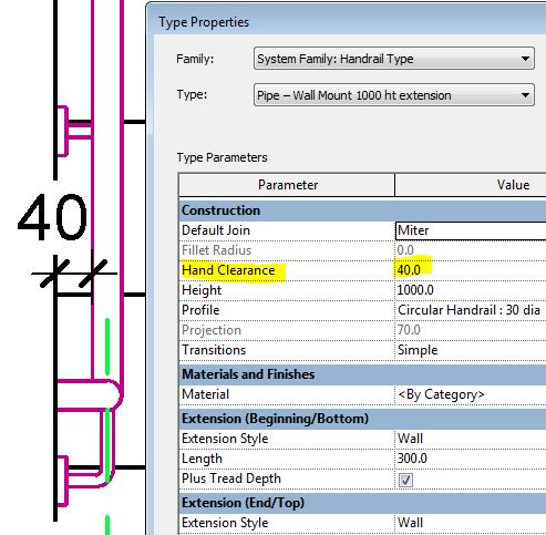
Handrails can only be moved laterally within the Handrail Type Properties (not in the railing properties).  This is controlled by a property called 'Hand Clearance'


The Hand Clearance property dictates how far the inside face of the Handrail is offset from the 'Notional Railing Centreline', which is not necessarily where the wall or other railing elements are*.

  • The Handrail family has a ‘Hand Clearance’ property, and projection property (see below)
  • In trying to use a real-world term, Autodesk have muddied the waters and made it totally confusing to work with.  This property is only logical with certain types of railings:
    • one example might be a wall-mounted handrail that has no other linear elements; and even then it only works when the Railing 'Offset from Path' property is set to zero.
    • If the railing has balusters and posts, with a Handrail mounted on those, the ‘Hand Clearance’ property does not take account of the baluster/post width, so you'd need to add in half that width yourself.

Once the Hand Clearance property is set in the Handrail family, you have to go back to the Railing family to see the effect it has on the whole railing, where the calculated Lateral Offset is displayed (not shown in the Handrail properties).

The Lateral Offsets are calculated by the system, depending on the Handrail type properties.  Typically this should be:
  • Hand Clearance + (Profile Width / 2)    - in this case  40 + 30/2 = 55mm.  
  • The Lateral Offset represents the centreline of the Handrail relative to the notional centreline of the whole railing (which is itself moved around by the 'Offset from Path' property).
  • If you want a centred Handrail, you need to make its hand clearance property minus half the profile width
Projection Property
  • There is another calculated property that is displayed here: 
    'Projection', which is calculated as (Hand Clearance + Profile Width)
    It is again greyed out, and updates immediately after any changes to the profile width or Hand Clearance.
  • I cannot see the logic of having this property displayed here, while the Lateral Offset is not.

Changing Properties

The knock on effects of any changes you make is again, a little confusing:
  • If you change the profile type, and hence its width then the 'Hand Clearance' is likely to change.  What Revit is trying to do is maintain the 'Lateral Offset' value, and hence the centreline location of the Handrail.
  • This may be logical to the software programmers, but not to designers, who would want to maintain the Hand Clearance when the profile width changes.  
  • The end result is that you need to pay careful attention, and manually change the Hand Clearance yourself after every profile change.
Once you have made any changes to the Handrail Type properties, then click OK, it returns to the Railing Type properties (if that is where you started from).  There is a display bug here:
  • The Lateral Offset does not appear to be recalculated (although it is).
  • To cause a display refresh, you need to change the value of the 'Position' to something else, and then back again.
  • Alternatively you could close the Type properties and reopen.

Wall-Mounted Handrails

In the case of Wall-Mounted Handrails, where there are no Top Rails or Balusters, the settings need to be somewhat different - and this is about the only situation where the term 'Hand Clearance' makes any sense.

The Railing Instance property 'Offset from Path' needs to be set to zero.  It is very frustrating that this is not a Type property, or at least have a default value stored within the Type properties - as you need to remember to set it to zero every single time you place a railing of this type.

The Handrail Type properties should be set with the actual Hand Clearance that you want - say 40 or 50mm.

Make sure that you choose the correct profile size first, as Revit will alter the Hand Clearance if you change the profile.

The Railing Lateral Offset property will be set automatically.


Top Rail Offsets

  • The Top Rail family also has a ‘Hand Clearance’ property, and projection property.
  • This is confusing - the Top Rail is meant to be there to support other railing elements, although it may double as a handrail. Whether it serves as a handrail or not, it would typically be centred with balusters etc on the 'Notional Railing Centreline', which is what the Hand Clearance value is measured from. 
  • Just to make it doubly confusing, the Top Rail offset is inconsistent with Handrail offsets:  a positive Hand Clearance value moves the Top Rail outside the stair in plan (Handrail moves inside stair).
  • Although the calculation for Lateral Offset is the same, it moves the opposite way:
    • (Hand Clearance + Profile Width / 2) - in this case  -25 + 50/2 = 0mm
  • If you want a centred Top Rail, you need to make its Hand Clearance property minus half the profile width of the Top Rail.

If you set the Hand Clearance to zero, you would get a Top Rail offset by half its width from all the balusters (unless they also had offsets . . .)


Here is  more information on the inconsistency between Top Rail and Handrail Terminology