BILT Speaker

BILT Speaker
RevitCat - Revit Consultant
Showing posts with label segment. Show all posts

Tuesday, 8 February 2022

Stepped Handrail on Stepped Stairs in Revit

A couple of years back I posted on how to create a stair with stepped sides


I always intended to follow it up with what happens to the handrail, and how to solve it?  Well, it is never too late.


Just in case you are wondering how to create the stepped side to the stair run in sketch mode - here is a trick for creating a DIY array in Revit.


When you create a stepped boundary for a stair run, the handrail also becomes stepped, but it is pretty clunky.


Baluster Placement

The first thing to notice is the hideous baluster placement - it is placing one at each change of direction, and one (or more) in the middle of each segment.

To tidy it up:

  • we will probably have to create a new railing type (to avoid messing up the straight railing on the other side of the stair
  • then edit the railing type properties; and the baluster placement
  • Untick the checkbox for 'Use baluster per tread on stairs'


  •  Balusters will only be placed at ends of each segment

Alternatively you could try the opposite: keep the Baluster per tread, but remove the start and end balusters - but then you lose control of the baluster locations in the segments running parallel to treads (not centred).


Top Rail Properties

You may not like the clunky Art Deco look of the vertical "Gooseneck" handrail segments, so the first step is to tab-select just the top rail (not the whole handrail) - then look at its Type properties

  • Change the Transitions from 'Gooseneck' to 'Simple' (or None)
  • Revit will give a not very helpful "not continuous rail" warning:
  • Whichever you choose (Simple or None), you get 'None', as Revit has a headache and thinks it is all too difficult, so it simply can't be bothered to join the segments

Edit Railing Segments

The next thing to try is editing the whole railing path:

  • Select the handrail
  • Edit the path

  • Select the first path segment at the base of the stair
  • Check its properties, displayed on the Option Bar
  • Change the Slope from 'By Host' to 'Sloped'

  • Finish the Sketch
  • Nothing appears to happen to the railing slope!  We will solve that later.
  • Edit the path again
  • Select the next segment that should be sloping (3rd from end)
  • Change its Slope to 'Sloped'
 
This is getting tedious, so let us try a couple of shortcut:

  • Instead of finishing the sketch to see how it looks, you could try the cool new Railing "Preview" feature in the ribbon menu (in a 3D view)
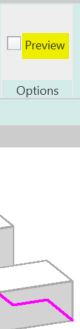
 

  • Tick the Preview checkbox
  • Aaaargh - it does not work when you adjust railing segment properties! It does not show the adjusted slope property.  You still have to Finish the sketch to see the effect


  •  Edit the path again
  • Select several segments to change their Slope property
  • Aaargh - the properties are not shown on the Option Bar when you select multiple segments!
  • Change the Slope properties for every alternate segment - one by one!
  • Finish the Path sketch

Something is wrong with the overall height of the railing when compared to the straight railing on the other side of the stair.  

  • This can be checked in an elevation view

Height Correction

To solve this, one way is to change the Height Correction property of each segment:
  • Edit the railing path again
  • Select the first segment
  • Change its Height Correction property to Custom; with a value to match the riser height
  • Finish the Path sketch
  • The railing height is now correct (more or less)
  • The lowest segment is now sloping

  • Check it in elevation


Now who has a headache?  Not just Revit!

This is a crazy amount of work to do in order to get this sort of correct.

Of course, you could avoid all this by just putting in a straight diagonal railing, but the point of this blog is to demonstrate the problems with stairs and railings - and to show workarounds (however nasty they may be).   There may also be situations where the diagonal railing is not appropriate - perhaps where the stepped sides are much larger steps.




Monday, 18 December 2017

Weird Railing Stuff - part 10 - Split railings

[Edit:  Revit 2019 has a new feature that allows you to split a railing - but all it does is to break the selected railing into two separate pieces that no longer relate to each other.  They can then be separately edited.   But just supposing you wanted to have a single railing element that has a gap in it?  Read on . . . .]
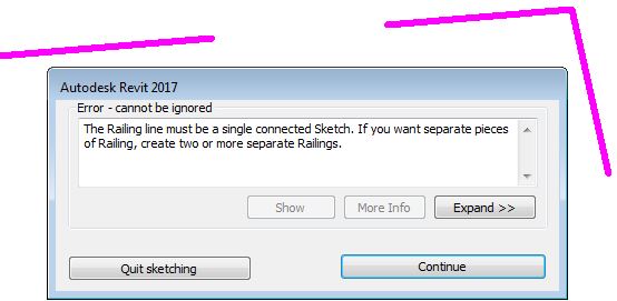
Have you ever tried to create a Revit railing with a split or break in it?  You'd have seen the warning that tells you it is not possible in Revit:

Split Revit Railings

Well, there is a way to do it - yes you can split railings (with lots of provisos, of course).
WARNING: this is another crazy workaround, so use it with caution . . .

In this example, a railing runs through a column, which is not desirable


You may want to break the railing and have a gap either side of the column

The first thing to do is edit the path of the railing, remove the top segments and stop it short of the column by say 50mm.


Once the top part of the railing is removed, Tab-select the 'Top Rail' (or Handrail) - it is important to select one of these sub-elements, not the overall railing.  NB. if your railing does not have either of these sub-elements, this technique won't work (eg. old style top rails)

Once selected, click on 'Edit Rail'

Then click on 'Edit Path' for the Top Rail

This will allow you to add lines to either the top or bottom end of the Top Rail element; but first it is important to set the workplane depending on whether you are adding to the beginning/bottom or end/top.

Select the name of the workplane.   I don't think that either of the 'Pick' options work here.

The workplane will be parallel to the first or last segment of the overall railing - so you'll need to work in either a 3D view or an elevation/section view.  It may be easier to start in 3D so that you can see exactly what you are doing and where.

This command is not explicit about what is going on - in fact Revit is waiting for you to draw some lines, which will become extensions to the Top Rail (or Handrail)

These lines do not need to be directly linked to the ends of the Top Rail - in fact they can be almost anywhere (in the same plane as the end of the Rail).  Start drawing a line the other side of the column from the end of the railing;  at this stage it may be easier to go into a section/elevation view to ensure that it aligns with the railing on the other side of the stair (but keep an eye on the active workplane).

Trace over the other railing (it should snap to it).

Once the Top Rail extension is complete, it will have a gap where the column is.


Be warned:  This is an extension to the Top Rail only - so balusters will not be attached to the underside of the extension.

Supports will not be attached to a Top Rail, so if you require supports on the extension, make sure before you start that your railing has a 'Handrail' sub-element, and add the extension to the Handrail, not to a Top Rail.  If you switch the railing to a type that does not have a Top Rail, the entire extension will disappear (if it was attached to a Top Rail in the first place).  Plan ahead!


Not surprisingly, this workaround is fiddly and not particularly robust - but I am showing it just in case it helps someone out.  In this example, it would probably have been much easier (and safer) to have two separate railings, but it might give people ideas about a use for this technique, so go for it.

Downsides:
  • Only works with a Top Rail or Handrail in the railing
  •  Top Rail and Handrail extensions are not interchangeable
  • Top Rail cannot host supports
  • Will not host balusters or posts beyond the split
  • Will not turn corners in plan
  • Will not automatically adjust heights/angles if the stair changes
  • Is quite confusing for anyone not familiar with railing extensions

Thursday, 14 April 2016

Weird stuff with Revit Line Weights

Following on from my previous post about line weights for material patterns, I have found some more weird things about Revit line weights that I never knew before:

1.  Pattern Line Weights

As Frank Giorlando rightly pointed out in a comment on the previous post:  Ceiling surface patterns use Line Weight 2.  So, if you want to control those independently, you should start your regular line weights from #3.
Thanks for that tip, Frank.

It would not surprise me if there are other categories that use different line weights again.

2.  Apply Button

The "Apply" button on the Line Weights dialog box does not appear to work - so if you start changing settings for different scales and want to check what happens (with hatching lines for example), you have to click OK to close the dialog box to see the effect.  I wasted a bit of time making changes that did not seem to be having any effect before I realised.  (as of Revit v2016 R2)

3.  Grid Line Weights

In testing the previous bug, I discovered some more weird settings:
Gridlines have all sorts of hidden away weight controls -
Unlike most elements, the actual grid line weight numbers are controlled from the grid Type properties (not from the Object Styles settings).  However, the Grid Heads have a master control in Object Styles where you might expect the gridlines to also be controlled

And something else I never knew:  The type properties for grid lines allow you to set different line weights, colours and styles for the centre and end segments - by choosing 'Custom' Center Segment..


Why would anyone want this?  I guess someone out there needs it and the programmers thought it would be useful.  Personally I would have been happy to see the weight set in Object Styles, with Visibility Graphics overrides if you need them - like most other categories.  This just seems like an unnecessary complication and inconsistency.

[Edit: Steve Stafford has previously blogged about how and when to use the Center Segment setting in this link.  I can see that you might well want to have a gap in the grid, but I still can't imagine why anyone would want a different line weight - just to make their drawings look ugly?  This also highlights the radically different way to control breaks in the middle of gridlines vs breaks in the middle of section lines - oh, I wish we had more consistency in UI and methodology in Revit]

4.  Dimension Tick Line Weights


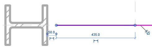
Another category where the line weights are controlled in the Type Properties is Dimension lines.  The line itself and the dimension 'Tick Mark' have independent weight settings (at least both appear to be in the same place, unlike grids and grid heads).

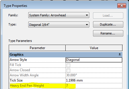
But when you go to the arrowheads dialog box and check the settings for the Tick Mark, there is another weight control called "Heavy End Pen Weight".  Now someone is showing their age by using the term "Pen" in there!  Most of the time it is greyed out and has no effect, but if you cycle between the different Arrowhead Types, each one has a different value.  Why?

Well, if you change the Arrow Style to 'Heavy End Tick Mark' it enables that setting and you can change the number.  If you change the Arrow Style back to Diagonal or Arrow, it greys out the number but remembers it - I guess it does nothing.  I decided that I do not want to know what a Heavy End Tick Mark is nor why it needs its own special setting that causes confusion to the other arrow styles - it is a 'rabbit-hole' I don't want to go down any further!

Note the mix and match of imperial and metric units that came straight out of the v2016 metric sample file.  Sloppy work by someone there!

[Edit: Steve Stafford has blogged previously about when you might use Heavy End Tick Marks in this link]

Really Weird:  Line weights in Perspective Views

Friday, 14 August 2015

Part 2 - Creating Revit Swept Blends along sinuous multi-segment paths


In my previous blog post I described some of my attempts to create a swept blend along a sinuous multi-segment path.

What I ended up with last time was a form created by selecting a series of profiles hosted onto the nodes of a divided path (without selecting the sweep path as part of the form).   In this example I had to indent the ends of the divided path so that the profiles were more or less linear and Revit could create the form.
 
Each of the profiles has an instance height parameter so that it could be easily adjusted to give an undulating form
My next task was to extend the form back the full length of the Divided Path.  I used a similar technique in a previous post where I had hosted points on a spline.  In this case it seemed easier because I could adjust the Divided Path properties by changing its 'Beginning and End Indent' rather than selecting individual points.
Going for broke and setting it right back to zero certainly did not work - it was unable to create the form.  Technically I was only trying to modify the form - so it would be interesting to know if the warning message is telling the truth:  is it actually recreating?  or modifying, in which case the dialog box wording is wrong.
A less dramatic change to the beginning indent from 3700mm to 3000mm was still too much for Revit.
Finally I had to settle for a mere 50mm change to the beginning and 400mm at the end - not enough to make a significant difference
I tried recreating the form with more profiles, spaced more closely - but that did not work either, when I tried reducing the indents
So I came to the conclusion that Revit is just not capable of creating a sinuous swept blend form like this if you do not include the path in the form creation.

Spline Logic

So that took me back to an idea that I had rejected earlier on:  tracing a spline over the chain of arcs/lines in order to achieve a single element path for the swept blend.  And, I needed the spline to follow the arc chain as closely as possible, and preferably to adjust when the underlying arcs are changed.
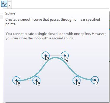
  • Just hovering the cursor over the spline tool was enough to tell me that it would be hopeless, as you cannot snap to the arcs - it would all be guesswork and lots of adjustment later on
 
  • The 'Spline by Points' tool is more promising as the spline goes through specific points exactly
  • This tool works in two different ways - you can just start drawing the spline and it places points as you click.  But I made the mistake of trying the second method which involves placing points first then selecting them so the command links them into a spline.
  • Revit did not create the spline in the order that I placed the points, nor in the order I picked them - it was seemingly random.  Perhaps this explains why it could not create forms earlier, out of my series of profiles - if it uses the same strange logic to decide the order
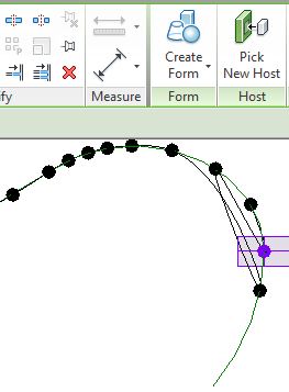
  • With this technique, you could re-host the points into the right order by selecting each point, and using 'Pick New Host' to put it where it should be - a very laborious process.
 
  • It is much better to use the spline command by the first method of placing them on the arcs in the order you want - and it hosts the points on the arcs nicely.
  • You need to place a reasonable number of points, especially in areas where the arcs switch direction or curve tightly - the reason for this is that the spline will not follow the arcs exactly, so more points will make it more accurate
  •  You can slide points along the arc to improve the accuracy - providing you put enough points on each arc
  • Once the spline is created, you could host profiles directly onto the spline points.  That would be fine if you just wanted a smooth transition between two profiles at start and end.  If you want an undulating shape, there are two reasons I would not host the profiles on the spline points:
1.  The orientation of the profiles will most likely be different to when they were hosted on divided path nodes.  In this example I got lucky and they were correct:

2.  You would need to place every profile.  It is much easier to create a divided path and host one profile onto a node, then repeat it.  In this example I was unlucky and the orientation was different to the original divided path!  This is typical of Revit - the mysteries of why a divided path on a series of arcs vs on a spline will produce nodes that have different xyz orientations is just that:  a mystery.  I will write another blog post on that subject some other time.
  • For the sake of this example, let us assume it was the same orientation so we could just go ahead and 'Repeat' the profile, then dissolve ('Remove') the repeater.
  • To create the form, you need to select all the profiles AND the spline (not the divided path)
  • Now the length of the swept blend should be adjustable easily by changing the divided path indents.  
  • The heights of each profile can be changed to give it an undulating shape
  • The first and last profile can have very small width and height to taper the shape
  • If you hide the profiles (by subcategory) you'll get a cleaner shape
  • The profile could be made of a single half ellipse, as in in the next example - to eliminate the horizontal joint lines
  • Finally you have a beautiful piece of undulating furniture.  Or a Loch Ness monster, depending on your project.

Anyone who has read this far will agree that this is a tortuous process (pun intended), riddled with workarounds.  The main purpose of this blog post is to demonstrate to the software developers how complicated it is to create some forms in Revit - how many roadblocks there are in the software; how many workarounds you have to learn; and how long it takes.  If anyone has learnt any tricks along the way, that is a bonus.

There are other programs around that could do this in minutes rather than hours (or days) - but they lack the precision of being able to document something that is buildable and follows a more geometric basis, such as a series of arcs rather than splines.  So I would much rather be able to do this in Revit to start with.

Related topics: