BILT Speaker

BILT Speaker
RevitCat - Revit Consultant
Showing posts with label adaptive. Show all posts

Saturday, 13 April 2019

Revit Conceptual Massing Environment - Index


Over the years I have struggled with the Conceptual Massing Environment (CME) in Revit.  It is not easy to use, and is not at all well integrated with the rest of Revit.  However, I have learnt a huge amount about how to get it to do what you want (or not!).  I have tried to document some of the tips and tricks on this blog and during various conference presentations that I have given at RTC & BILT .

Here is a summary / index of all the relevant posts on this blog:

Conceptual Massing Environment

Rival Revit Environments - Traditional vs Conceptual Massing Environment (CME)


Creating Traditional Forms using Conceptual Massing

Part 1 - Extrusion 
             Extrusion Offset Properties
Part 2 - Blend
Part 3 - Revolve
Part 4 - Sweep
Part 5 - Swept Blend
Part 6 - Loft
 
Part 7 - Hybrid Swept Blend / Loft


Revit Nurby Forms at BILTANZ

Adaptive Components

Adaptive Components

Adaptive components are a subset of the Conceptual Massing Environment:

Repeaters

Repeaters are a kind of array, in the CME world . . .

Modelling Santiago Calatrava's Gare do Oriente (Lisbon) using Repeaters:
Step 5  Assembling the Array of Structural Columns


Revit Ideas - Vote to Improve the Conceptual Massing Environment in Revit:


Some of the problems could be alleviated by the following capabilities - please vote for them on the Autodesk Revit Ideas wish-list if you agree:


Wednesday, 29 August 2018

Creating Swept Blends in Revit Mass - CME Part 5

Part 5 of my series on  comparing the five traditional form creation tools with equivalent techniques in the Revit Conceptual Massing Environment.
Previously we analysed the creation of extrusion forms, Blends, Revolves, and Sweeps in the CME.  Next up is Swept Blends:

Part 5:  Swept Blends

Creating a Swept Blend in the Conceptual Massing Environment. . . .

  • A swept blend requires two or more profiles, each perpendicular to the path ;
  • In the traditional Revit environment, a swept blend can only have two profiles;
  • Unlike a sweep, the path can only consist of one element (line, arc or curve), even if the profiles are closed;
  • Unlike a sweep, the profile cannot contain a loop within a loop (to make a hollow form);
  • The easiest way to do this is to host the profiles on points – in the example here, an arc has 3 points that define it, so they can also be used to host the profiles


  • The profiles can be model lines, reference lines or loaded 2D profile components - each method has its own advantages or disadvantages (described below) depending on how you want to modify the form later on, so there is no clear 'best method';
  • Create Form by selecting the profiles and the path
  • In this example, the profiles are the same shape, so there is a smooth transition, and you cannot even see the middle profile
  • NB. If you had just selected the profiles, Revit would decide its own path, which may not match the one you created – in which case the form would become a ‘Lofted’ shape

Edit Form

Editing behaviour differs, depending on the original profiles and path:

  • For model line profiles, you can use ‘Edit Profile’ – it will prompt you for which profile to edit, so you may need to put the form into X-Ray mode to be able to select the middle profile(s) or use wire-frame mode
  • In sketch mode you can modify the profile, or change it entirely
  • However, if you don't have the same number and type of segments in each profile, it may result in sharp edges
  • Try matching the segments in each profile, to make the transitions smooth, without edges  

  • For reference line profiles, the profiles can only be changed in size/proportion, depending on how much you can manipulate the reference lines without breaking the profile (but you cannot add segments)
  • For loaded component profiles, they can be parametrically controlled (best method), but you cannot reload a profile with a different configuration or number of segments 

 Point Hosting

  • The Autodesk help files recommend putting the profile(s) onto points hosted on the path (rather than using the points that define the path in the example above) – this has several advantages: it should give more control with moving end points and rotation


  • Unlike a sweep, when you create a form, it does not extend along the whole path – only between the first and last profile


If you adjust the path underneath, the form follows it:


If the profiles were model lines, then the lines and host points on the path are ‘consumed’, which means the host points cannot be selected or manipulated, and the model lines have limited controllability (except in edit profile sketch mode).

Dissolve


If the form is dissolved the model lines and points are kind of reinstated but not to exactly their original state:
  • Circles are split into semi-circles
  • Points lose their display status
For this reason, you may need to recreate or rehost the profiles after dissolving a form, and reset some properties.


Loft vs Swept Blend

The important thing to note with Swept Blends is that the path is included during the creation of the form, but does not become part of the form itself;  when the path is modified, the form changes too.
If the path is not included, the form becomes a 'Loft'. 

The inclusion of the path can be extremely useful when it comes to modifying the form - as will be seen later . . .

Youtube

For more info on this, view the Youtube video:
Create a swept blend in Revit CME


Monday, 18 June 2018

Extrusion Offset properties in Revit CME

Following on from the description of creating extrusions in the Conceptual Massing Environment, here is another subtlety regarding properties of extrusions in the CME.

Offset Properties 

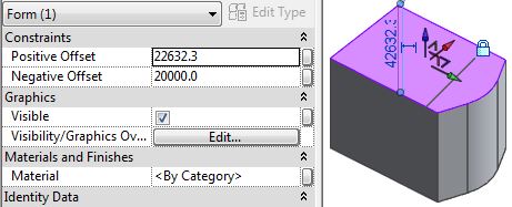
Locked extrusions have 'Positive & Negative Offset' properties, that drive the distance of the end facets from the original profile.  These behave in different ways depending on exactly how the extrusion was created and locked.

Reference Line Extrusions

  • Create Form using reference lines as the profile
  • Creates an extrusion, which is automatically locked
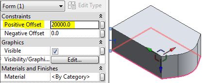
  • The form has Positive and Negative Offsets, relative to the reference lines


  • Select the base facet, drag down

  • Negative offset value
  • Reference lines remain in original position


  • Unlock the extrusion - no offset properties


Model Line Extrusion

  • Create Form using model lines as the profile
  • Extrusion is not locked  automatically
  • Does not have offsets

  • Select the top facet
  • Lock the form to an extrusion
 
  • Padlock does not appear (unless you reselect the form)
  • It now has Offsets, relative to top facet (not the base, which was the original profile)
  • Drag the top facet up and it shows a positive offset
  • The Negative Offset is the position of the bottom facet relative to the original position of the top when it was locked - there is no visible record of that location.
  • Undo
  • Edit profile
  • It does not ask you which profile to edit (as it is locked)
  • Revit goes into Sketch edit of the top facet (not the base, which was the original profile)

  • Cancel
  • If you were to 'Dissolve' the form at this stage, you would end up with only the top facet, which is in a different location to the original profile.
  • Do not proceed with 'Dissolve'; or Undo, if you did.
  •  Unlock the extrusion form (the Offset properties disappear)
  • This time, select the bottom facet (or a line/edge on it)

  • Lock Form
  • Offsets now relate to bottom facet - more logical in this situation

  • Edit Profile
  • Sketch edit is now the bottom facet (original model line profile)


The moral of this tale is that you need to plan very carefully when creating extrusions - first choose whether to use model or reference lines;  If you chose model lines (which allow easy editing of the profile to add/remove segments) then choose a line/edge carefully before locking the profiles.

Conclusion

A real life example of when this would be important is the creation of a 'context' model for your site:
You want to model adjacent buildings as simple extrusions, and you want to control their height by typing in known RLs, without having to calculate heights.
  • As you probably want to work in context in a project, you might create an in-place mass family;
  • However, it could also be done in an external family, as a generic Adaptive Component (with no adaptive points), changed to a site category;
  • Draw the profiles on a Datum level (or reference plane) at RL zero (or round number, say 100 or 1000 metres)
  • Choose model lines for easy profile editing (or reference lines for stability);
  • Create Form
  • Deselect the top facet
  • Select a line on the base
  • Lock Profiles
  • Select the top facet
  • Type in the RL (in mm) for the building height

  • You could also adjust the base facet height using a minus value in the negative Offset property to represent the RL of the base of the building

Wednesday, 15 March 2017

Nested Revit Repeaters - Gare do Oriente pt 5

How to use Revit adaptive components and repeaters to create a model of Santiago Calatrava's roof structure of the Gare do Oriente in Lisbon:
Part 1 - The rig for one structural column
Part 2 - Placing roof panels onto the rig
Part 3 - Creating the structural elements 
Part 4 - Adding struts to the structure

Part 5 - Assemble Structure on Platforms

YouTube Link


Step by Step checklist:

Add Column Base

  • Open your column structure adaptive family created in steps 1 - 4
  • Set the work plane as the horizontal reference plane of adaptive point 1
  • Place a reference polygon centred on the adaptive point, first making it 4 sided
  • It will give four temporary dimensions, one for each side, from the centreline references
  • Make these into real dimensions
  • Select all four dimensions and associate them to a parameter called 'Half base'
 
  • Optional:  create a new parameter called Base Width
  • Optional:  add a formula to 'Half base' = Base Width /2
  • Select the four reference lines of the polygon
  • Create form
  • Drag its top surface up, and it should enable a temporary dimension for the height
  • Turn that into a dimension
  • Associate it to a parameter 'Base Height'
  • The family is now ready to use in a project model


Create an Array of Columns

  • Load the family into a project
  • Create railway platforms (floors or extrusions of some kind) 
  • Create an in-place Mass family
  • Draw a rectangle of reference lines, with the two long sides centred on the outside platforms
  • The length of the rectangle should be a multiple of the distance between each platform
  • Select the four reference lines (rectangle)
  • Create a form
  • Drag the top surface of the form up or down so that it is flush with the top of the platforms
  • Select the top surface of the form
  • Click on the 'Divide surface' icon
  • Depending on the number of platforms/tracks, and the length of the rectangle, adjust the number of U and V grid divisions to achieve a square pattern of grids, one per platform - remembering that the number matches the grid lines not the divisions
  • Change the surface representation of the divided path; make the Nodes visible
 
  • Place one of the structural adaptive components onto any one of the nodes
 
  • Select the component and click on the Repeater icon
  • It should create an array of columns, one on each node
  • Select the divided surface and hide its nodes again, so that they will not be visible in the project in any views.  NB. if any divided path nodes are visible in the structure, you need to hide those back in the family and reload them (which can be painfully slow, so its better to do so before creating the repeater) 
  • Finish the Mass family
  • In the project Browser, select the column family and change its 'Inside Radius' property to match half the spacing between nodes (platforms) - this should ensure that the overall size of the roof matches the divided surface grid size
  • Adjust any of its other properties as desired - eg. Base Height
  • The individual nested families will most likely be shared families, unless you changed that when creating them - so you should be able to adjust other parameters by selecting the nested families in the project browser - eg. Number of struts. NB. it can be slow to make those property changes depending on your computer, but remember that Revit is doing a lot of calculating for each change, and it is still much quicker than creating such a structure by conventional Revit modeling tools.
  • You should now have a basic parametric model of the railway station roof of Santiago Calatrava's Gare do Oriente in Lisbon


Tuesday, 7 March 2017

Revit Nested Repeaters - Gare do Oriente part 4

How to use Revit adaptive components and repeaters to create a model of Santiago Calatrava's roof structure of the Gare do Oriente in Lisbon:
Part 1 - The rig for one structural column
Part 2 - Placing roof panels onto the rig
Part 3 - Creating the structural elements 

Part 4 - Struts

Now it is time to really challenge the nesting capabilities of  'Repeaters' in Revit by placing struts on the structure.
Gare do Oriente structural element with struts added

Here is a YouTube link to see it as a tutorial

YouTube:

Step by Step Checklist

In case you prefer reading it step by step:
  • Open the 'one-eighth' adaptive component created in the previous blog post
  • Select the structural elements and temporarily hide them, to leave the rig visible
  • Place two hosted points each on the arc and two of the reference lines
 
  • Link the points with reference lines - in the case of the arc, snap to the intersection point along the middle of the arc (NB. make sure 3D snapping is on)
  • The purpose of placing new shorter reference lines over the top of the existing ones is to create a rig for the struts to snap to the ends of those shorter lines while still being offset from the adaptive points
  • Select the 3 points near the start of each line/arc - remembering the direction you placed the lines/arc
  • Associate the Normalised Curve Parameter to a parameter called 'Segment proportion'

  • Select the other 3 points near the end of each line/arc
  • Change their Measure From properties to 'End'
  • Associate their Normalised Curve Parameter to 'Segment proportion'

  • Select the reference arc, click on the 'Divide Path' icon
  • Repeat this for each of the two reference lines
  • Select the 3 new Divided Paths
  • Associate their number of divisions with a new parameter 'Number of Struts'
 
  • Add a formula to the Segment proportion parameter:
  • Segment proportion = 1 / (Number Struts + 1)
  • This will make the distance each hosted point is from the adaptive points to be equal to the segments on the divided path
  • Flex the Number of Struts parameter to make sure the divisions change and the end points move

Create the Struts

  • Open the previously created 2 point adaptive tube family
  • Save it as a 3 point strut family
  • Add another point in free space
  • Make it adaptive (point 3)
  • Place a reference line between points 2 and 3
  • Place 2 hosted points on the line
  • Make their Show Reference properties to be Always visible
  • Change their Measurement Type properties to 'Segment Length'
  • Change the Measure From property of the second point to 'End'
  • Associate their Segment Lengths to the 'Offset from End' parameter
  • Set the work plane to be the reference plane of the first point
  • Place a reference circle on the point
  • Give it a radius dimension and associate it to the Radius parameter
  • Repeat for the second point - add a reference circle
  • Select both circles and the host reference line
  • Create Form - it should create a second tube
 
  • Flex the parameters and the adaptive point locations
  • Load the V-shaped strut into the other adaptive family

Place the Struts

  • Place a component, snapping to the divided path nodes on each path - it is important to select the same node number on each one
  • It is better to avoid the end nodes so that you don't accidentally snap to a host point - choose nodes one in from the end
  • Select the strut
  • Click on the Repeater icon
  • If the divided path host references were all created in the same direction, it should create a regular pattern of struts
  • Flex the number of struts parameter and the adaptive point locations
 
  • It should overwrite the family already placed on the rig (without struts), and display all the struts
  • Try flexing the dimensions and the number of struts

The last stage is to add a base and place the columns on the station platforms . . . .TBA