Previously we analysed the creation of extrusion forms and Blends in the CME. Now it is the turn of 'Revolves' (pun intended):
Part 3: Revolves
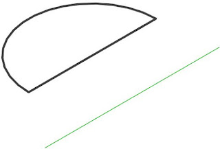
Creating a Revolve in the Conceptual Massing Environment is relatively simple, but it does not give you the option to nominate the Axis of Rotation - you just have to draw a straight line and hope that Revit figures out which element you want to use as the axis:- Draw a straight line (for the axis of rotation) and a profile (closed or open)
- Select them both and ‘Create Form’
- If the profile is closed it will just create the revolve (maybe!);
- If the profile is open, it will suggest two options: a revolve or a flat surface connecting the line and profile
- A closed profile can allow a nested loop to create the form, but only if the profile is made from lines – not from a loaded family profile
- This is only one of two situations that I have found where you can include a loop within a loop during the 'Create Form' process in the Conceptual Massing Environment.
Once the Revolve has been created, the form will have properties for Start and End angle - these can be changed to reduce the form from a full 360 degree revolve.


No comments:
Post a Comment