BILT Speaker

BILT Speaker
RevitCat - Revit Consultant
Showing posts with label environment. Show all posts

Saturday, 13 April 2019

Revit Conceptual Massing Environment - Index


Over the years I have struggled with the Conceptual Massing Environment (CME) in Revit.  It is not easy to use, and is not at all well integrated with the rest of Revit.  However, I have learnt a huge amount about how to get it to do what you want (or not!).  I have tried to document some of the tips and tricks on this blog and during various conference presentations that I have given at RTC & BILT .

Here is a summary / index of all the relevant posts on this blog:

Conceptual Massing Environment

Rival Revit Environments - Traditional vs Conceptual Massing Environment (CME)


Creating Traditional Forms using Conceptual Massing

Part 1 - Extrusion 
             Extrusion Offset Properties
Part 2 - Blend
Part 3 - Revolve
Part 4 - Sweep
Part 5 - Swept Blend
Part 6 - Loft
 
Part 7 - Hybrid Swept Blend / Loft


Revit Nurby Forms at BILTANZ

Adaptive Components

Adaptive Components

Adaptive components are a subset of the Conceptual Massing Environment:

Repeaters

Repeaters are a kind of array, in the CME world . . .

Modelling Santiago Calatrava's Gare do Oriente (Lisbon) using Repeaters:
Step 5  Assembling the Array of Structural Columns


Revit Ideas - Vote to Improve the Conceptual Massing Environment in Revit:


Some of the problems could be alleviated by the following capabilities - please vote for them on the Autodesk Revit Ideas wish-list if you agree:


Thursday, 27 September 2018

Creating Lofts in Revit Mass - CME Part 6


Here is part 6 of my series on  comparing the five traditional form creation tools with equivalent techniques in the Revit Conceptual Massing Environment.
Previously we analysed the creation of extrusion forms, Blends, Revolves, Sweeps and Swept Blends in the CME.  Hang on - part 6 of 5?  Oh that's right, there is no way to create 'Loft' forms in the traditional Revit environment:

Part 6:  Lofts

It is possible to create a 'Loft' in the Conceptual Massing Environment - it is a little different to a Swept Blend, and has its own rules (and problems).  A loft is a 3D form made by linking a series of planar profiles to create a surface(s), which can be flat, faceted, curved or double-curved (NURBS).  I consider a loft to have a minimum of 3 profiles, as 2 would just be a 'Blend'.  The profiles are linked along a notional path - the difference between this and a Swept Blend is that the latter uses a specific path element, and a loft does not.  Revit will figure out its own path (or not, as the case may be!).


As soon as the edges are not aligned and you have 3 or more profiles, you will get curved surfaces – Revit creates its own spline edges.


The greater the displacement between profiles, the more dramatic the curves


The profiles do not have to be parallel to each other, but as soon as they are at different angles it becomes less predictable as to whether Revit will create the form as you desired. In the example below, the profiles were hosted on reference planes, which can be rotated, but only before the ‘Create Form’ process


Revit may not create the form at all, and you might get this error message:


If the error mentions 'Self-intersecting geometry', it may be due to Revit getting the profile order wrong such that it tries to create a form that doubles back or crosses over itself - something that Revit does not like one little bit.  When you select the profiles in the first place, it makes no difference which order you select them - you have absolutely no control over the order that Revit uses in the Create Form function.  It is not clear how Revit decides on the order - it may be proximity to each other?  However, I don't think it is that simple.

The second part of the error message talks about the 'Reorder Profiles' button - this is not usually visibly apparent.  There is a blank space for it in the bottom left corner of the dialog box.  Wouldn't it be nice if Revit tried to Create Form again with a different profile order;  better still if it asked you to nominate the order!

About once in every few hundred times you get this dialog box, there will actually be a 'Reorder Profiles' button.  Be very careful about clicking on it.  The first time I tried that, Revit crashed out and closed without saving anything.  Thus it is wise to save all files before attempting this.


If you do click on the button, it won't help!  If it doesn't crash, it will just fail again.  It would seem that one of the programmers was aware of this form non-creation ability of Revit, and they tried to add a solution.  However, it seems like this functionality was removed from Revit before it was released to the unsuspecting public.  Sadly one instance of the many variations to the dialog box still has the button there to tantalise us.

If you would like Autodesk to fix this, please go to the Revit Ideas wishlist and vote for this enhancement request:

Control profile order during form creation


This description of Loft creation shows a very simple example - it can get quite complex.  There are many tips and tricks as to how to make Loft form creation easier and more predictable in Revit.  More to follow later . . . .

Saturday, 5 May 2018

Revit Nurby Forms at BILT ANZ 2018 in Brisbane


I am looking forward to the next BILT ANZ Conference in Brisbane on 24 - 26 May 2018, where I will be presenting a session on creating 'Nurby Forms in Revit' - ie. creating complex forms with NURBS surfaces (double-curved), which are notoriously difficult in the Revit Conceptual Massing Environment.

In this session I will start by looking at using the Conceptual Massing Environment to create the equivalent traditional Revit 3D forms (Extrusion, Revolve, Sweep, Blend, Swept Blend), and examining the subtleties of different methods.  This will inform the next stage of creating sinuous forms in Revit, and the workarounds you'll need to overcome some of Revit's limitations.  Then I will demonstrate some techniques for creating parametric NURBS forms that you would not expect Revit to be able to handle.  Finally I will look at how to make these forms look better, as Revit is not good at displaying NURBS.  All this will be done without using any API, Dynamo or Add-ins of any kind.


Hope to see you at BILT in Brisbane for my session:  #1.3 'Create Good Looking Organic Nurby Revit Content' at 1.45 on Thursday 24th May 2018.


Friday, 14 August 2015

Part 2 - Creating Revit Swept Blends along sinuous multi-segment paths


In my previous blog post I described some of my attempts to create a swept blend along a sinuous multi-segment path.

What I ended up with last time was a form created by selecting a series of profiles hosted onto the nodes of a divided path (without selecting the sweep path as part of the form).   In this example I had to indent the ends of the divided path so that the profiles were more or less linear and Revit could create the form.
 
Each of the profiles has an instance height parameter so that it could be easily adjusted to give an undulating form
My next task was to extend the form back the full length of the Divided Path.  I used a similar technique in a previous post where I had hosted points on a spline.  In this case it seemed easier because I could adjust the Divided Path properties by changing its 'Beginning and End Indent' rather than selecting individual points.
Going for broke and setting it right back to zero certainly did not work - it was unable to create the form.  Technically I was only trying to modify the form - so it would be interesting to know if the warning message is telling the truth:  is it actually recreating?  or modifying, in which case the dialog box wording is wrong.
A less dramatic change to the beginning indent from 3700mm to 3000mm was still too much for Revit.
Finally I had to settle for a mere 50mm change to the beginning and 400mm at the end - not enough to make a significant difference
I tried recreating the form with more profiles, spaced more closely - but that did not work either, when I tried reducing the indents
So I came to the conclusion that Revit is just not capable of creating a sinuous swept blend form like this if you do not include the path in the form creation.

Spline Logic

So that took me back to an idea that I had rejected earlier on:  tracing a spline over the chain of arcs/lines in order to achieve a single element path for the swept blend.  And, I needed the spline to follow the arc chain as closely as possible, and preferably to adjust when the underlying arcs are changed.
  • Just hovering the cursor over the spline tool was enough to tell me that it would be hopeless, as you cannot snap to the arcs - it would all be guesswork and lots of adjustment later on
 
  • The 'Spline by Points' tool is more promising as the spline goes through specific points exactly
  • This tool works in two different ways - you can just start drawing the spline and it places points as you click.  But I made the mistake of trying the second method which involves placing points first then selecting them so the command links them into a spline.
  • Revit did not create the spline in the order that I placed the points, nor in the order I picked them - it was seemingly random.  Perhaps this explains why it could not create forms earlier, out of my series of profiles - if it uses the same strange logic to decide the order
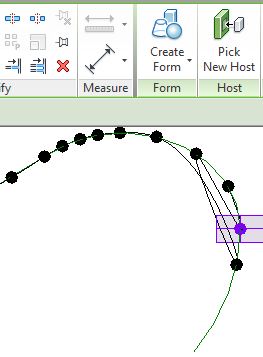
  • With this technique, you could re-host the points into the right order by selecting each point, and using 'Pick New Host' to put it where it should be - a very laborious process.
 
  • It is much better to use the spline command by the first method of placing them on the arcs in the order you want - and it hosts the points on the arcs nicely.
  • You need to place a reasonable number of points, especially in areas where the arcs switch direction or curve tightly - the reason for this is that the spline will not follow the arcs exactly, so more points will make it more accurate
  •  You can slide points along the arc to improve the accuracy - providing you put enough points on each arc
  • Once the spline is created, you could host profiles directly onto the spline points.  That would be fine if you just wanted a smooth transition between two profiles at start and end.  If you want an undulating shape, there are two reasons I would not host the profiles on the spline points:
1.  The orientation of the profiles will most likely be different to when they were hosted on divided path nodes.  In this example I got lucky and they were correct:

2.  You would need to place every profile.  It is much easier to create a divided path and host one profile onto a node, then repeat it.  In this example I was unlucky and the orientation was different to the original divided path!  This is typical of Revit - the mysteries of why a divided path on a series of arcs vs on a spline will produce nodes that have different xyz orientations is just that:  a mystery.  I will write another blog post on that subject some other time.
  • For the sake of this example, let us assume it was the same orientation so we could just go ahead and 'Repeat' the profile, then dissolve ('Remove') the repeater.
  • To create the form, you need to select all the profiles AND the spline (not the divided path)
  • Now the length of the swept blend should be adjustable easily by changing the divided path indents.  
  • The heights of each profile can be changed to give it an undulating shape
  • The first and last profile can have very small width and height to taper the shape
  • If you hide the profiles (by subcategory) you'll get a cleaner shape
  • The profile could be made of a single half ellipse, as in in the next example - to eliminate the horizontal joint lines
  • Finally you have a beautiful piece of undulating furniture.  Or a Loch Ness monster, depending on your project.

Anyone who has read this far will agree that this is a tortuous process (pun intended), riddled with workarounds.  The main purpose of this blog post is to demonstrate to the software developers how complicated it is to create some forms in Revit - how many roadblocks there are in the software; how many workarounds you have to learn; and how long it takes.  If anyone has learnt any tricks along the way, that is a bonus.

There are other programs around that could do this in minutes rather than hours (or days) - but they lack the precision of being able to document something that is buildable and follows a more geometric basis, such as a series of arcs rather than splines.  So I would much rather be able to do this in Revit to start with.

Related topics: