BILT Speaker

BILT Speaker
RevitCat - Revit Consultant
Showing posts with label CME. Show all posts

Saturday, 2 June 2018

Creating Traditional Revit Forms in the Conceptual Massing Environment


In my recent presentation at BILT ANZ 2018 in Brisbane - Creating Nurby Forms in Revit, I started off by analysing how the traditional Revit 3D form creation tools can be matched in the Conceptual Massing Environment.

  
Traditional 3D form creation in Revit has 5 predefined sketch-based tools – these are well understood by most Revit users. They are also very limited when it comes to creating double-curved or organic shapes.

Unlike these, the newer Adaptive/CME form creation methods (from Revit 2010 onwards) are somewhat of a mystery to many users – the logic is completely different, and there is only one ‘Create Form’ command.   However, it is capable of creating much more organic shapes than the traditional tools.

I have previously listed an extensive comparison between the 'Rival Revit Form Creation Environments'.  In this series of blog posts I will go into much greater detail on the subtle inconsistencies between each form creation method.  Understanding these 'exceptions to the rule' make the whole Conceptual Massing Environment (CME) much easier to work with - I use the word 'easier' rather than 'easy', because the CME is never easy!!

One of the big differences between the old and new methods is the ability to ‘Loft’ shapes in the CME, or to use multiple profiles in a swept blend:
  • The traditional environment allows the creation of a ‘Swept Blend’, which creates a single transition from one 2D profile to another – while this does allow some double curved surfaces, the transition between the two is constant along the path of the swept blend;
  • The CME also allows the creation of a Swept Blend along a path, but the big difference is that it allows more than two profiles – this allows the transition to be controlled and changed at any point along its path. There are many ways to achieve this but unfortunately Revit has a number of significant limitations in what kinds of forms it will create (more on this later).
  • The CME ‘Loft’ function allows the use of multiple shapes/profiles to control the transition from first to last, without selecting a path.
 There are many more differences that will be described in the following posts.

CME shape creation methods

The CME Create Form function only has one icon, with no user controlled options - and it works in several different ways, depending on what elements you select:
  • Single shape/profile (chain of arcs/lines/curves) – creates an extrusion of the profile. It can be an open profile that creates a surface, or a closed profile that creates a solid form, in which case it puts end surfaces on the extruded form
  • One profile plus a path - creates an extrusion or sweep (can be multiple segment path for closed profiles) 
  • One profile plus a separate straight line - creates a revolve
  • Multiple profiles plus path – creates a swept blend (single element path only)
  • Multiple profiles without path – creates a loft form
  • By hosting elements along a path then selecting all the elements (but not the path) – it creates a hybrid swept blend / loft 
It is not clear to the user how Revit decides which creation method to use and how it decides which element defines a profile, and which is a path or axis, nor the order of multiple profiles.  This is the crux of the problem - in simplifying the User Interface to a single command icon, Autodesk have robbed the users of predictability and real control over the end result.

Some of the problems could be alleviated by the following two capabilities - please vote for them on the Revit Ideas wish-list if you agree:

Control profile order during form creation

Nominate Path during form creation

Traditional Methods in the CME


Each of the traditional form creation methods (plus lofting) are examined in the Conceptual Massing Environment in the following blog posts (links will be enabled as each is posted):
1.  Extrusion 
     Extrusion Offset Properties
2.  Blend
3.  Revolve
4.  Sweep
5.  Swept Blend
6.  Loft
7.  Hybrid Swept Blend / Loft

Path

The form creation path (if used) can be model or reference lines or edges of another form or component
  • Path can be a single arc, line or curve (Revit help refers to all of these as a line)
  • Sometimes it can be a multiple chain of elements – for closed profiles on sweeps only
  • It cannot be a ‘divided path’ element

Profiles

The form creation profiles can be:
  • Model or reference lines (chained) or 
  • Edges of a form or 
  • Loaded components - 2D model lines (planar) within a component (adaptive or traditional of most categories, but not a traditional 2D profile family)
  • Must be a single chain of lines, arcs, curves (open or closed profile);
  • Very occasionally Revit allows a loop within a loop;
Depending on the original profile, the form behaves quite differently - It makes a big difference whether you use Model lines or Reference lines:
  • Model lines are ‘consumed’ by the form and can be edited later (Edit Profile);
  • Reference lines are retained as an underlying rig for the form – and they can be independently edited to change the form (can only be moved/stretched);
  • Reference line extrusion forms are automatically locked; model line extrusion forms are not;
  • Component profiles are not consumed, and can be changed if parametric;
If you host points onto a path, and then host profiles on those points (as recommended by Autodesk), there are differences in behaviour once a form is created from the profiles:
  • Model line profiles – the host point gets consumed too. It cannot be selected or moved; it loses any properties & associations to parameters (eg. for offset from end of host path); to move the profile along the path, you have to select it, not the host point – which has no parametric control;
  • Reference lines – the host point retains all its properties and associations, so it can be moved along the path parametrically (profile goes with it)

There are other subtle differences, to be explained later - in the individual form creation method posts.

Adaptive components 

Adaptive Components are a special kind of Revit family that operate in the CME world (not traditional family editor forms)
  • They are similar to Mass families but can have multiple insertion points
  • They can be of some different categories (but not mass) – somewhat limited
  • Cannot be created in-place in a project

Repeaters

Repeaters are a kind of array, in the CME world
  • Made up of adaptive components hosted on divided paths or surfaces within a mass or adaptive family, which are then arrayed using the ‘Repeater’ function.
  • Profiles within the repeaters can be used to create forms, with some limitations – the Repeater first has to be dissolved; the divided path cannot be used as a form creation path.

Saturday, 5 May 2018

Revit Nurby Forms at BILT ANZ 2018 in Brisbane


I am looking forward to the next BILT ANZ Conference in Brisbane on 24 - 26 May 2018, where I will be presenting a session on creating 'Nurby Forms in Revit' - ie. creating complex forms with NURBS surfaces (double-curved), which are notoriously difficult in the Revit Conceptual Massing Environment.

In this session I will start by looking at using the Conceptual Massing Environment to create the equivalent traditional Revit 3D forms (Extrusion, Revolve, Sweep, Blend, Swept Blend), and examining the subtleties of different methods.  This will inform the next stage of creating sinuous forms in Revit, and the workarounds you'll need to overcome some of Revit's limitations.  Then I will demonstrate some techniques for creating parametric NURBS forms that you would not expect Revit to be able to handle.  Finally I will look at how to make these forms look better, as Revit is not good at displaying NURBS.  All this will be done without using any API, Dynamo or Add-ins of any kind.


Hope to see you at BILT in Brisbane for my session:  #1.3 'Create Good Looking Organic Nurby Revit Content' at 1.45 on Thursday 24th May 2018.


Friday, 14 August 2015

Part 2 - Creating Revit Swept Blends along sinuous multi-segment paths


In my previous blog post I described some of my attempts to create a swept blend along a sinuous multi-segment path.

What I ended up with last time was a form created by selecting a series of profiles hosted onto the nodes of a divided path (without selecting the sweep path as part of the form).   In this example I had to indent the ends of the divided path so that the profiles were more or less linear and Revit could create the form.
 
Each of the profiles has an instance height parameter so that it could be easily adjusted to give an undulating form
My next task was to extend the form back the full length of the Divided Path.  I used a similar technique in a previous post where I had hosted points on a spline.  In this case it seemed easier because I could adjust the Divided Path properties by changing its 'Beginning and End Indent' rather than selecting individual points.
Going for broke and setting it right back to zero certainly did not work - it was unable to create the form.  Technically I was only trying to modify the form - so it would be interesting to know if the warning message is telling the truth:  is it actually recreating?  or modifying, in which case the dialog box wording is wrong.
A less dramatic change to the beginning indent from 3700mm to 3000mm was still too much for Revit.
Finally I had to settle for a mere 50mm change to the beginning and 400mm at the end - not enough to make a significant difference
I tried recreating the form with more profiles, spaced more closely - but that did not work either, when I tried reducing the indents
So I came to the conclusion that Revit is just not capable of creating a sinuous swept blend form like this if you do not include the path in the form creation.

Spline Logic

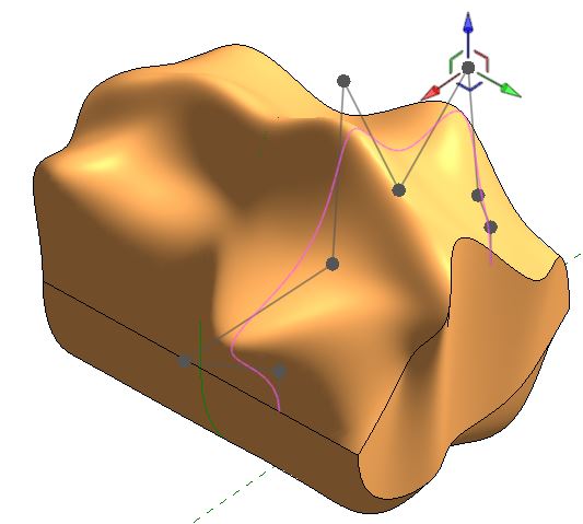
So that took me back to an idea that I had rejected earlier on:  tracing a spline over the chain of arcs/lines in order to achieve a single element path for the swept blend.  And, I needed the spline to follow the arc chain as closely as possible, and preferably to adjust when the underlying arcs are changed.
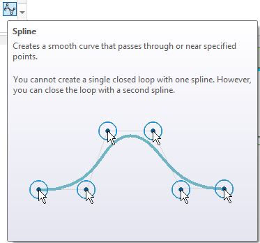
  • Just hovering the cursor over the spline tool was enough to tell me that it would be hopeless, as you cannot snap to the arcs - it would all be guesswork and lots of adjustment later on
 
  • The 'Spline by Points' tool is more promising as the spline goes through specific points exactly
  • This tool works in two different ways - you can just start drawing the spline and it places points as you click.  But I made the mistake of trying the second method which involves placing points first then selecting them so the command links them into a spline.
  • Revit did not create the spline in the order that I placed the points, nor in the order I picked them - it was seemingly random.  Perhaps this explains why it could not create forms earlier, out of my series of profiles - if it uses the same strange logic to decide the order
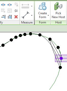
  • With this technique, you could re-host the points into the right order by selecting each point, and using 'Pick New Host' to put it where it should be - a very laborious process.
 
  • It is much better to use the spline command by the first method of placing them on the arcs in the order you want - and it hosts the points on the arcs nicely.
  • You need to place a reasonable number of points, especially in areas where the arcs switch direction or curve tightly - the reason for this is that the spline will not follow the arcs exactly, so more points will make it more accurate
  •  You can slide points along the arc to improve the accuracy - providing you put enough points on each arc
  • Once the spline is created, you could host profiles directly onto the spline points.  That would be fine if you just wanted a smooth transition between two profiles at start and end.  If you want an undulating shape, there are two reasons I would not host the profiles on the spline points:
1.  The orientation of the profiles will most likely be different to when they were hosted on divided path nodes.  In this example I got lucky and they were correct:

2.  You would need to place every profile.  It is much easier to create a divided path and host one profile onto a node, then repeat it.  In this example I was unlucky and the orientation was different to the original divided path!  This is typical of Revit - the mysteries of why a divided path on a series of arcs vs on a spline will produce nodes that have different xyz orientations is just that:  a mystery.  I will write another blog post on that subject some other time.
  • For the sake of this example, let us assume it was the same orientation so we could just go ahead and 'Repeat' the profile, then dissolve ('Remove') the repeater.
  • To create the form, you need to select all the profiles AND the spline (not the divided path)
  • Now the length of the swept blend should be adjustable easily by changing the divided path indents.  
  • The heights of each profile can be changed to give it an undulating shape
  • The first and last profile can have very small width and height to taper the shape
  • If you hide the profiles (by subcategory) you'll get a cleaner shape
  • The profile could be made of a single half ellipse, as in in the next example - to eliminate the horizontal joint lines
  • Finally you have a beautiful piece of undulating furniture.  Or a Loch Ness monster, depending on your project.

Anyone who has read this far will agree that this is a tortuous process (pun intended), riddled with workarounds.  The main purpose of this blog post is to demonstrate to the software developers how complicated it is to create some forms in Revit - how many roadblocks there are in the software; how many workarounds you have to learn; and how long it takes.  If anyone has learnt any tricks along the way, that is a bonus.

There are other programs around that could do this in minutes rather than hours (or days) - but they lack the precision of being able to document something that is buildable and follows a more geometric basis, such as a series of arcs rather than splines.  So I would much rather be able to do this in Revit to start with.

Related topics:

Sunday, 15 December 2013

Rival Revit Environments - Traditional vs CME

For the first decade of its life, Revit really only had one method of creating 3 dimensional forms - in the Family Editor (aside from those generated by system families).  When Revit 2010 was released we suddenly had a whole new way of doing things with the new conceptual massing tools.  Since then, many people have been grappling with the seeming divergence of these two very different Revit environments.  Now we have the prospect of such tools as Dynamo introducing yet more ways to work in Revit - however exciting it seems, Dynamo has the potential to cause even more disparity and fragmentation of not only the workflow but the development effort by Autodesk.  This has been worrying me for some time, and I've been thinking about how best to convey our concerns to Autodesk in a positive constructive way.

Recently I was reading Paul Aubin's new book:
Renaissance Revit:  Creating Classical Architecture with Modern Software
In chapter 1 he discusses some of the differences between the Traditional Family Editor and the Massing Environment (Conceptual Massing Environment or CME as Autodesk refers to it).  I realised that there are a whole lot more differences, that are not clearly documented anywhere, so I thought I would try to address the issue here.

Before I do that, a little more about Paul's book: 

Although the overall intent of the book appearsto be about using Revit to create classical architectural elements, it is in fact all about using Revit to create some tricky geometry - and the techniques that he describes could be used for all sorts of purposes.  For example, in chapter 4 he describes how to constrain arcs, circles, elipses and splines that might be used to parametrically control families.  I wish I had read that before embarking on my own exploration of the subject, which had nothing to do with classical architecture - it would have saved me a lot of time and effort.   The early chapters of the book also set out a lot of good practise that anyone should apply when creating Revit families, for whatever purpose.

Skipping on to Chapter 11 gives us a good general introduction to creating families in the Conceptual Massing Environment before launching into ways to apply that specifically to classical architecture.  Again, these principles are relevant to many other situations when building Revit models.  Thanks Paul for a fascinating new book.

Traditional Family Editor vs Conceptual Massing Environment


Below is an analysis of the differences between the traditional Revit Family Editor and the Conceptual Massing Environment, follwed by some specific differences that apply to Adaptive Components - these generally follow the massing methodolgy but have a few more quirks of their own.  The table below is compiled from some of Paul's observation and some from my own experiences of working with adaptive components in particular.  This is not a definitive list, and I may have made errors or omissions.  Please feel free to comment, and I may update the list in the future, based on feedback.

I hope that Autodesk can make use of this analysis to help bring the two rival Revit environments back together in the future – and I use the word rival quite deliberately because they seem to be fighting each other much of the time.

I have traffic-light colour coded the comparisons:


Red = Bad
Orange = Getting there
Green = Good

Conceptual Massing Environment
Traditional Revit
3D work environment
·      Offers greater flexibility
·      Can be very confusing
·      Need to continually set work plane;
·      Can pick work plane on the fly just by picking level or reference plane
·      But it is easy to make mistake with work plane
·      Levels visible in 3D (but not for in-place massing)
·      Reference planes visible in 3D (but not for in-place massing)
·      Reference lines used extensively to generate forms or host elements
2D work environment
·      Limitations  when working with unusual shapes in 3D
·      Simple, familiar workflow (for Revit users)
·      Work plane often set automatically by the view; 
·      Can set reference plane as work plane only if named first
·      Must use set work plane command (unless prompted)
·      Hard to make a mistake with work plane
·      Levels not visible in 3D
·      Reference planes not visible in 3D
·      Reference Lines used almost exclusively for controlling angles
Levels
·      Can create multiple levels within family (but not In-Place CME) 
·      Created levels do not relate to levels in project
Levels 
·      Cannot create multiple levels within family (unless already in template)
·       Upper level in columns & 2 level Generic model family do relate to project levels
3D forms created from selected elements
·      Greater flexibility
·      Harder to understand 
·      Unpredictable – eg. Cannot nominate which element is for path (result is a guessing game) 
·      Easy to make mistakes
·      Often fails to create form
3D forms are sketch-based, on a 2d work plane
·      Limited range of 3D forms
·      Simple to understand 
·      Predictable – eg. Sweep path is nominated    
·      Hard to go wrong once learnt
·      Seldom fails to generate form (usually understandable when it does – eg lines zero length)
3D forms “unlimited” 
·      Limited by what you can draw, and by certain software limitations (unknown so can’t be listed here!)
·      Can be solid or void
·      Boolean combinations –  does allow solid to cut solid
·      Boolean operations can be confusing (must control picking of form vs surface)
 ·      Cannot create form from loop within loop (must use void to cut out shape)
·      Can loft multiple selected shapes, which can be at varied angles

 ·     Profile for Extrusion etc can be closed (for solid forms) or open (for surfaces); Open profiles require a single element path

·      Sweep along a path can have multiple linked elements to define its path (2d or 3D) but it can be tricky to define (arcs, lines and/or curve)
 ·      Swept blend along a path can only have one element to define its path (arc, line or curve)
 ·     Can loft multiple selected shapes, which can be at varied angles to each other
Five basic 3D forms
·      Limited to: Extrusion, Blend, Revolve, Sweep, Swept Blend
·      Can be solid or void
·      Also limited boolean combinations of above (join & cut)
·      Extrusion, sweep allows loop within loop
·       Profile for Extrusion, Blend, Revolve, Sweep, Swept Blend must always be closed (to create solid forms)
·       Can only create blend between 2 shapes - with “blend” (ends must be parallel) or “swept blend” (ends perpendicular to ends of sweep path).

·      Sweep  along a path can have multiple linked elements to define its path (arcs, lines and/or curve); Path can be in 3 dimensions but only by pick line function, otherwise only in 2d if sketched
 ·      Swept blend along a path can only have one element to define its path (arc, line or curve)
·       No loft tool
Profile families
·      Cannot use traditional 2d profile families to generate forms in CME – but can use flat generic adaptive families (easy enough but different methodology).
·       2D Profile cannot have loop within loop
Profile families
·      Can use traditional 2d profile families to generate forms

·      2D Profile can have loop within loop
Editing Forms
·      Forms can be changed from one type to another (extrusion to blend to loft etc)
·      Lock/Unlock Profile command to enforce extrusion
·       Add Profile command available
·      Boolean commands to cut or combine forms
Editing Forms
·      Forms cannot be changed from one type to another – each of the five primitives are not interchangeable
·      Profiles, sweep paths, and dimensions can be changed easily
·      Boolean commands to cut or combine forms
Editing shapes of profiles
·      Complex rules;  easier to make mistake
·      Depends on how the lines/form were created:
o  Base  reference lines can be moved without editing profile
o  From lines and profile is “locked” – can edit
·      Edit Profile command sometimes available (like trad. edit sketch)
·      Add/remove segments in Edit Profile mode
·      Add Edge command sometimes available
Editing sketch profile
·      Very simple;  almost foolproof
·      Select form, “Edit Sketch”
·      Adding/removing segments very simple in sketch mode
Changes to Work Plane of profiles in forms   
·      Somewhat complex and not intuitive:  need to select original elements that were used to create form – only works if reference lines;  model lines get consumed by form, so cannot select them.
·      Can only change work plane of selected elements to a parallel plane
·      Extrusion with “locked profile” will display Positive and Negative Offsets if top or bottom face is selected;  (but work plane of original lines is not displayed at the same time) – so it is possible to change location of a top face relative to bottom face (not possible with blend or loft)
·      User can place a dimension for the height of the form, but this involves extra steps; it stops temporary dimensions working for that face;
·      If the height dimension is turned into a parameter it may remove spot elevations and shape handles of forms back in the project environment
Changes to sketch profile Work Plane   
·      Very simple – “Edit Work Plane” or “Pick New” commands available to relocate original sketch and thus modify or move form
·      Using “Pick New” work plane, can totally change orientation of an extrusion or blend.
·      Extrusion or blend have properties:  Workplane; First End; Second End so it is easy to change the opposite end of the form by amending End property.
Identify or Change absolute location of a face in CME (eg. If you need to know RL of top of an extrusion)
 
·      This is a nightmare!  It is really difficult:
·      Extrusions display a positive & negative offset for a face only if profile is locked – therefore it won’t work for a blend
·      Work plane property is only displayed in a separate dialog box; and only if the original reference planes are selected; not possible with model lines.
·      It is not possible to place a Spot Elevation annotation in the CME
·      If you place a Spot Elevation annotation onto an in-place mass before editing, the annotation disappears as soon as you edit – so you cannot see the RL as you drag the face of an extrusion!
·      In the project environment, if you drag the face of an extrusion (mass family) using the shape handle, an attached Spot Elevation will not update dynamically – only updates after you let go the handle
Identify or Change absolute location of a face in Model In-Place family (eg. Need to know RL of top of an extrusion)
·      Very simple: Edit Family; select form to see properties
·      Extrusion or blend have properties visible in same dialog box:  Work Plane; First End; Second End (dimensions) so it is easy to know its absolute location.
·      Easy to change Second End property of extrusion or blend to an absolute location (assuming base work plane is a level, grid or named reference plane)
·      It is not possible to place a Spot Elevation annotation within In-Place family
·      If you place a Spot Elevation annotation onto an in-place family before editing, the annotation disappears as soon as you edit – but this is not so bad because it easy to identify RL from work plane + second end property
·      In the project environment, if you drag the face of an extrusion (in-place family) using the shape handle, an attached Spot Elevation will update dynamically
Panelling
·      Divided surfaces can only be done within CME, not in project environment
·      Divided surfaces are fairly flexible (grids or intersects),
·      Divided surfaces are not always predictable or easy to control
·      Curtain Panel Pattern families are special types of components that can only be applied or modified as patterns within the CME.  This is very “unRevit-like”.
·      Only Curtain Panel Pattern or Adaptive families can be applied to a divided surface as a pattern of panels or repeater – but this must be within CME
·      Adaptive and Curtain Panel Pattern components can be individually placed on divided surface nodes (only if visible) in CME – they will move with changes to nodes
Panelling
·      Curtain walls and systems can be placed in the project environment; 
·      Curtain wall/system divisions are limited
·      Curtain wall/system divisions are fairly predictable
·      Panels in curtain walls and systems are regular components that follow normal Revit rules
·      It is not possible to apply a traditional Revit family to a divided surface as a pattern of panels (or suchlike) – it may be technically possible by nesting, but that is not a realistic option
·      Adaptive components can be placed on divided surface nodes (only if visible) in Project Environment – but they will not move with changes to nodes.  NB. Node visibility can only be changed by editing the mass family.
Categories - CME
·      Mass family cannot be changed to other categories
·      Adaptive families can be changed to some limited other categories (but not to structural)
·      Adaptive families cannot be changed to mass category
Categories - Regular family
·      Regular family can be changed to many other categories but not to mass, adaptive or system  (except by obscure workarounds)
·      Changing category will inherit some characteristics of new category but depends on what is normally in pre-set templates
File size & performance - CME
·      much larger files
·      multiple nesting can increase size significantly
·      can run very slowly, especially with multiple nesting
File size & performance
·      smaller  files
·      multiple nesting only increases size a small amount
·      run moderate to fast depending on formulas and nesting
Line selection in CME
·      Chain of lines is automatically highlighted for selection (this is mighty confusing and wastes much more time than it could ever save)
Line selection in traditional family editor / project environment
·      Chain of lines is only highlighted for selection using the tab key
Copy and Paste
·      Cannot copy and paste into CME from traditional family
·      Cannot copy and paste from project environment into CME
Copy and Paste
·      Cannot copy and paste into traditional family from CME
·      Can copy and paste lines from project environment into traditional family editor (limited)
Nesting
·      Cannot nest CME or Adaptive families into traditional families
Nesting
·      Can nest traditional families into CME or Adaptive
Group command not available
Group command is available
Create Similar command not available
Create Similar command is available for in-place families
Does not have “Annotation” tab in the ribbon
·      Cannot place text
·      Cannot place symbols
·      Cannot place Symbolic Lines
·      Cannot place Detail Components
·      Cannot place Detail Groups
·      Cannot place Masking Region
·     Does not have model text.
·     only way to get any kind of text/label/tag into a mass or adaptive component is to nest a generic component that has model text in it
Does have “Annotation” tab in the ribbon
·      Can place most detail/annotations to represent 2D information in plans sections and elevations
·      Cannot place filled region in model families (have to be nested)

Divide line & Divide Surface available
·      Mismatch between numbers on divided path vs surface
·      Divided path/surface node visibility setting is obscure
·      Divided path/surface nodes visible in project (by default for path)
Divide line & Divide Surface not available
Arrays – in CME / Adaptive
·      Repeater command available
·      Repeaters relatively flexible but hard to predict
·      Repeaters can be 2 or 3 dimensional (inc radial)
·      Array command not available
Arrays
·      Repeater command not available
·      Array command available
·      Arrays very limited but predictable
·      Arrays only 2 dimensional or radial
Volume properties
[Edit. Not sure when this changed, but can now]
·      “Gross Volume” mass property can be scheduled or tagged
Volume properties
·      “Volume” property of forms in generic category (only) can be scheduled but not tagged
Control command not available
Control command available (for flipping components in project)
Visibility Settings only available by right-clicking
Visibility Settings available (for controlling display levels and 2d view visibility)
Parametrics & Formulas
·      Allows all available Revit formulas (with many limitations)
·      Reporting parameters can be used in formulas only if derived from Adaptive points (? No other “host” elements)
Parametrics & Formulas
·      Allows all available Revit formulas (with many limitations)
·      Reporting parameters can be used in formulas only if derived from “host elements” – ie. Baked into templates (eg. reference planes, levels, walls)

·      Global parameters allow reporting parameters attached to any linear/angular dimension in the project (but not for areas)

Here is a further analysis of the weird and wonderful (or not) quirks of trying to create equivalent traditional Revit 3D forms in the Conceptual Massing Environment
And more detail on individual form types:


A few more comparisons related specifically to Adaptive Components:

Adaptive Component Environment
Traditional Revit Family Environment
Can snap in 3d - this is a huge advantage, allowing easy creation of geometry in all kinds of directions in 3d.
·      3D snapping is off by default, leading to frequent errors
Cannot snap in 3d in family editor (big limitation in flexibility)
·      Limited line selection for 3d sweep paths
Placement of adaptive components in the project model:
·      Does not lock to orthogonal (bad news)
·      Does snap to vertices in 3d; 
·      adaptive points remain locked to vertices even when they move
·      Does not snap to toposurface even when category is “Site”
-   "Load Family" command is not available on the ribbon when placing a component  if an adaptive component is active in the Type Selector (In project and family editors)
Placement of regular components in the project model:
·      Does lock to orthogonal, and take advantage of all the Revit automatic snapping options
·      Only snap to vertices in 3d on a preselected work plane/surface; limited 3D line selection for beam placement
·      Does snap to toposurface when category is “Site or Entourage”
Voids in adaptive components:
·      Adaptive components cannot have a host element baked into the template – so It is not possible to include a void element in the adaptive component that will automatically cut the host face it is placed onto
·      “Cut with voids when loaded” capability is very limited in categories it can be applied to – it cannot cut curtain panels, curtain systems,  mass categories (big limitation). Only works in projects.
·      void repeaters have very limited usage – they can only be placed on flat surfaces of walls, floors, furniture, casework etc.  This is a huge wasted opportunity as it means that we cannot place void repeater patterns onto massing (to quickly represent windows on a mass model), curtain panels (perforated metal panels), or any curved surface of any category
Voids in regular components:
·      Some family templates have a host element baked into the template (face-based generic, doors, windows etc)– so It is possible to include a void element in the component that will automatically cut the host face it is placed onto
·      Regular components cannot be used in repeaters, so the “face-based” families with voids in them cannot be used

·      “Cut with voids when loaded”  only works in project, not in nested families

Point Elements
·      Points are available in CME and Adaptive components
·      Points can host  geometry and components
·      Points can be hosted on lines/arcs
·      Points can be used to control arc midpoints using “Start-End-Radius” arc (from v2014 only)
·      Placement of (Adaptive) points on Level work plane do not snap to reference planes in 3d views (but do in plan)
·      Points not available
Nesting
·      Traditional families can be nested into adaptive components
·      Nested family behaviour is unpredictable – particularly location and 2d rotation – behaviour changes radically depending on whether hosted on points or just placed on a work plane
·      Line based traditional families can be nested in, and two ends can be hosted on adaptive points
Nesting
·      Adaptive components cannot be nested into traditional families
·      Nested traditional family behaviour is fairly predictable – particularly location and 2d rotation
Hosting
·       Adaptive components can be hosted by adaptive points onto vertices in the project - in 3D (not constrained to planar placement)
·      Adaptive components will flex when  host vertices are moved, when adaptive points are snapped to vertices. 
·      Adaptive components are deleted if any one of its (possibly multiple) hosts is deleted - this is seriously bad news
Hosting
·   Traditional families can be hosted onto other elements in different ways depending on the family template and category - eg. Non-hosted; face-based; line-based; wall-hosted, ceiling-hosted, floor-hosted
·   Hosting behaviour is very inconsistent between different categories and templates - very confusing.
·   Hosting behaviour can be modified in the project by other settings and automatic system constraints. 
·   Family hosting behaviour cannot easily be changed (except by obscure workarounds)


3D Orientation
·      Adaptive families can be very unpredictable when placed in the project environment, especially when families are nested
·      Elements can be hosted on points, which have their own orientation controls – so that different parts of the model can be differently oriented
·      Options for point orientation are extremely confusing (even with the recent name changes)
·      Nested families can be oriented and located as part of the whole family or else controlled by points they are hosted on – can be very confusing
·      Nested components can orient themselves differently in the project environment to how they are oriented in their host family – can be very hard to manage (somewhat better from v2014 onwards)
3D Orientation
·      Most traditional families will be inserted into the project in the same orientation that they are modelled – the exception being face-based, or work plane based (where “Always vertical” is unticked).
·      The whole family is inserted in the same orientation
·      Nested families are oriented as part of the whole family, even if they have “Always Vertical” ticked (overridden by parent orientation in the project). Simple and predictable


See separate posts on Adaptive Components: