BILT Speaker

BILT Speaker
RevitCat - Revit Consultant
Showing posts with label spline. Show all posts

Friday, 14 August 2015

Part 2 - Creating Revit Swept Blends along sinuous multi-segment paths


In my previous blog post I described some of my attempts to create a swept blend along a sinuous multi-segment path.

What I ended up with last time was a form created by selecting a series of profiles hosted onto the nodes of a divided path (without selecting the sweep path as part of the form).   In this example I had to indent the ends of the divided path so that the profiles were more or less linear and Revit could create the form.
 
Each of the profiles has an instance height parameter so that it could be easily adjusted to give an undulating form
My next task was to extend the form back the full length of the Divided Path.  I used a similar technique in a previous post where I had hosted points on a spline.  In this case it seemed easier because I could adjust the Divided Path properties by changing its 'Beginning and End Indent' rather than selecting individual points.
Going for broke and setting it right back to zero certainly did not work - it was unable to create the form.  Technically I was only trying to modify the form - so it would be interesting to know if the warning message is telling the truth:  is it actually recreating?  or modifying, in which case the dialog box wording is wrong.
A less dramatic change to the beginning indent from 3700mm to 3000mm was still too much for Revit.
Finally I had to settle for a mere 50mm change to the beginning and 400mm at the end - not enough to make a significant difference
I tried recreating the form with more profiles, spaced more closely - but that did not work either, when I tried reducing the indents
So I came to the conclusion that Revit is just not capable of creating a sinuous swept blend form like this if you do not include the path in the form creation.

Spline Logic

So that took me back to an idea that I had rejected earlier on:  tracing a spline over the chain of arcs/lines in order to achieve a single element path for the swept blend.  And, I needed the spline to follow the arc chain as closely as possible, and preferably to adjust when the underlying arcs are changed.
  • Just hovering the cursor over the spline tool was enough to tell me that it would be hopeless, as you cannot snap to the arcs - it would all be guesswork and lots of adjustment later on
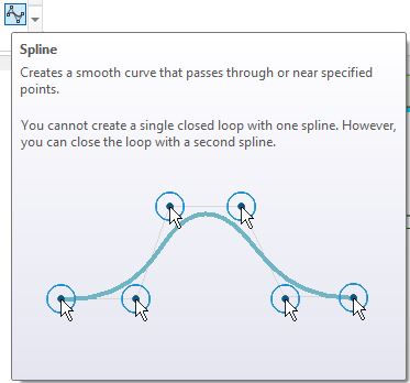
 
  • The 'Spline by Points' tool is more promising as the spline goes through specific points exactly
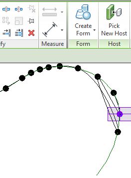
  • This tool works in two different ways - you can just start drawing the spline and it places points as you click.  But I made the mistake of trying the second method which involves placing points first then selecting them so the command links them into a spline.
  • Revit did not create the spline in the order that I placed the points, nor in the order I picked them - it was seemingly random.  Perhaps this explains why it could not create forms earlier, out of my series of profiles - if it uses the same strange logic to decide the order
  • With this technique, you could re-host the points into the right order by selecting each point, and using 'Pick New Host' to put it where it should be - a very laborious process.
 
  • It is much better to use the spline command by the first method of placing them on the arcs in the order you want - and it hosts the points on the arcs nicely.
  • You need to place a reasonable number of points, especially in areas where the arcs switch direction or curve tightly - the reason for this is that the spline will not follow the arcs exactly, so more points will make it more accurate
  •  You can slide points along the arc to improve the accuracy - providing you put enough points on each arc
  • Once the spline is created, you could host profiles directly onto the spline points.  That would be fine if you just wanted a smooth transition between two profiles at start and end.  If you want an undulating shape, there are two reasons I would not host the profiles on the spline points:
1.  The orientation of the profiles will most likely be different to when they were hosted on divided path nodes.  In this example I got lucky and they were correct:

2.  You would need to place every profile.  It is much easier to create a divided path and host one profile onto a node, then repeat it.  In this example I was unlucky and the orientation was different to the original divided path!  This is typical of Revit - the mysteries of why a divided path on a series of arcs vs on a spline will produce nodes that have different xyz orientations is just that:  a mystery.  I will write another blog post on that subject some other time.
  • For the sake of this example, let us assume it was the same orientation so we could just go ahead and 'Repeat' the profile, then dissolve ('Remove') the repeater.
  • To create the form, you need to select all the profiles AND the spline (not the divided path)
  • Now the length of the swept blend should be adjustable easily by changing the divided path indents.  
  • The heights of each profile can be changed to give it an undulating shape
  • The first and last profile can have very small width and height to taper the shape
  • If you hide the profiles (by subcategory) you'll get a cleaner shape
  • The profile could be made of a single half ellipse, as in in the next example - to eliminate the horizontal joint lines
  • Finally you have a beautiful piece of undulating furniture.  Or a Loch Ness monster, depending on your project.

Anyone who has read this far will agree that this is a tortuous process (pun intended), riddled with workarounds.  The main purpose of this blog post is to demonstrate to the software developers how complicated it is to create some forms in Revit - how many roadblocks there are in the software; how many workarounds you have to learn; and how long it takes.  If anyone has learnt any tricks along the way, that is a bonus.

There are other programs around that could do this in minutes rather than hours (or days) - but they lack the precision of being able to document something that is buildable and follows a more geometric basis, such as a series of arcs rather than splines.  So I would much rather be able to do this in Revit to start with.

Related topics:

Monday, 20 July 2015

Tightly Curved Swept Blends in Revit Adaptive/Massing Environment

Following on from my last post about 'Unable to Create Form Element' in the Revit Adaptive / Conceptual Massing Environment, here are a few ideas about how you might just solve the problem.

In the conventional family editor, Revit does not have any major problems in creating swept blends along a single path (one spline or arc or line), unless the radius of a curve on the sweep is too small and causes impossible geometry.  For example this simple sweep of a profile along a spline takes a minute or two to create:

In the Adaptive/Conceptual Massing Environment (CME) you have the added ability to loft shapes - to create blends of more than two shapes/profiles.  However, the rules for getting them to work are immensely more complicated, and often quite baffling.  Below is a particular workflow that I was using just to test a process, and it caused all kinds of issues.  Hopefully it might give you some clues as to how to solve similar problems - particularly if the path is more complex.

Creating Swept blends / Lofted Forms along a tightly curved path in CME

Workflow:
  • Place three points 
  • Select the points
  • Create a spline through the points
 
  • Adjust the spline to have a fairly sharp transition by dragging the middle point
  • Host some new points on spline
  • Host some adaptive profile components on the points
  • Select just the profiles
Select Profiles
  •  Create Form - it fails
  • Try pushing points closer together

  •  Select profiles; then create form - it might work if you are lucky
  •  Maybe you can pull the points back along the curve
  • At some point you get the 'No Entry' sign (circle with line through it), meaning it will not allow you to push the point that far along the spline
  • Try picking the control point for the spline and make it less of a tight curve
 
  •  Then maybe you can extend form by pushing the points out
  • If it is still not creating the form, you may need the spline to be really gentle to start with before you extend the points out to the ends of the spline
  • Point locations along the spline can be controlled by properties, or you can even make it parametric - using the 'Normalised Curve Parameter'.

  • Intermediate points may also need to move to get a better spread along spline
  •  Then try pulling the spline back to a tighter shape - Revit will most likely allow you to create a much tighter shape than it would originally
  • At some stage you'll notice that the form does not follow the spline, it just creates its own shape by linking the profiles
This may or may not be what you want.
  • If you do want it to follow the spline exactly, your life will be easier:
  • Dissolve the form
  • Select the profiles and the spline
  • Create Form again, and Revit will be much more forgiving - it is more likely to create the form with a tighter curve or one that turns more than 180 degrees on itself.  The obvious difference here is that it knows which order to link the profiles.
  • It uses the spline as a path but only extends between the first and last profiles
If you adjust the spline further, until the shape is too tight it will eventually tell you that it cannot create the form.  I have not figured out yet what the rules are.

What I have figured out is that if you go away for a while and drink a delicious cup of coffee brewed by your local barista (preferably a cappuccino), and come back to try again, you will usually have much more success with pulling the spline around into tighter curves with ends that even extend past each other (but not crossing).

Honestly, it is true that if you are too ambitious with the shapes initially Revit cannot cope.  But try adjusting them later and it works much better.  So the moral of the tale is that Revit gets a boost from caffeine just as much as you do.
More thoughts on lofting and swept blends to follow . . . .
Part 1 - Creating Sinuous Curve Swept Blends in Revit Adaptive/Massing Environment
Part 2 - Creating Revit Swept Blends along sinuous multi-segment paths

Wednesday, 7 January 2015

Revit Repeaters - RTC 2013 Competition Entry

Revit Repeater artwork
This image was part of my  entry for the drawing competition at RTC 2013, in the innovation category.  It was created using 100% Revit, without the use of Dynamo or any add-in APIs.  It was done to demonstrate some of the capabilities of the new "Repeater" command that was added to Revit 2013.

The museum building wall was created as a mass family, consisting of a curved spline in plan, extruded upwards to represent the outside facade;  its surface was divided into a rectangular grid.  A five point adaptive component panel was placed on one rectangle of the grid, with one of its points snapped to a common control point off the surface of the wall;  the panel was then repeated across the entire facade;  the size of the window in each panel was controlled by its distance from the control point - using the "reactor principle" described on Zach Kron's Buildz blog (a complex formula defined a sine-wave pattern for the change in window size).  Hopefully I will get time to document the technique on this blog eventually!

The artwork on the wall was done using two-way repeater pyramids that change shape depending where they are in the pattern - refer to how-to-schedule-panel-locations.

The people were single-point adaptive components consisting of lofted circles that had parametric diameters at various heights up the body, used to create different body shapes for each family type. The people outside were turned into repeaters by hosting six of them on divided splines, then using the repeat command - thus forming queues of people snaking into the museum entrance.

The signage on the roof of the museum was done with adaptive component (model text) repeaters that automatically rotate to face the camera - refer to my Mona-lisas-eyes-follow-revit-camera blog post.

The ground surface texture was done by creating a divided surface with slightly distorted adaptive components placed in a pattern of four and then repeated.

For more on this competition entry see the outdoor image of the museum

Sunday, 28 July 2013

Revit Scaleable Spline Tree Family

Having returned from RTC in Vancouver a couple of weeks ago, I decided to put into practice some of the things that I learnt at the conference.  It was another great Revit conference in a fabulous location - Vancouver is a beautiful city, and the waterfront has been really well designed and carried out.  Aside from catching up with friends, I met lots of interesting people and attended plenty of good classes.  Although I attended Marcello Sgambelluri's class on scaling families at RTC in Auckland, it was also a big talking point in Vancouver.  I asked several people if they had attended the class, and many enthusiastic people had;  some others said that they did not want to see how to scale a Revit cow or elephant - well they missed out on a treat, because we learned many tricks that could be applied to totally different areas of Revit. 

Here is one idea that I have developed based on one of the methods that Marcello used to scale classical column families:
Marcello Sgambelluri - Scaling Classical Order of Columns

Scale By Spline

This concept has also been explored by others, notably
Andy Milburn - Spline Sailing

but I first need to describe the concept here. 

A spline can be scaled just by dragging one of its end points.  To control this within a scaleable Revit family, you need to lock or attach the end points of the spline to something that you can dimension.  Although you can dimension the end points directly, it is better to use something like a reference plane.  Here is a simple rig to demonstrate this process:
The vertical reference planes and width parameter will be used to control the distance between start and end of the spline, and in turn its scale.
The offset reference plane and parameter are required in order to control the location of the spline.
Once the rig is set up, draw a spline between the two top reference plane intersections

Use the align tool to lock the ends to the reference planes, in both directions (4 locks required)

Change the width parameter to check that the spline is locked to the vertical reference planes and that it scales properly.
Change the Offset parameter to check that the spline is locked to the horizontal reference plane.

This example establishes the principle of being able to control scaling and location of splines using reference planes.  The spline end points do not need to be orthogonal to each other - they can also be at an angle.

Revit Scaleable Spline Tree Family

We can now apply this principle to multiple splines linked to each other, to create a simple tree family.  This example is proof of concept, and is only done in 2D, but it could be applied to 3D trees.

First make a rig of reference planes that are controlled by parameters
Then draw a series of splines between each reference plane intersection.
Lock the ends of the splines to the intersections using the Align tool (and then padlock)
Try flexing the overall height parameter - this will not only change the overall height, but it will not affect the other parameters.  So only parts of the tree will scale, and others will not be affected depending on how the parameters are arranged.  In this example, the tree trunk is not affected by the change in height - only the top part of the tree scales.
Changing the intermediate parameters will alter the overall shape as well as the width
 Different tree forms can be achieved by playing around with the parameters
One tree family can be used to create multiple tree types that vary in shape and height
By adding a few more reference planes and splines it should be possible to create a family that has independant tree height and spread parameters.  And all this can be done without having to nest one planting family inside another - it works without nesting.

No doubt there will be people who say that this is not practicable, or that the trees look terrible - but this is only a proof of concept.  I'm hoping that it will give more ideas to others who can run with the concept and create wonderful flexible tree families.