BILT Speaker

BILT Speaker
RevitCat - Revit Consultant
Showing posts with label scale family. Show all posts

Thursday, 28 November 2013

Geometric Patterns from Parametric Revit Stars

In my previous post I showed how to make a parametric star in Revit - one that has a variable number of points.  Here are some examples of how that might be used in a parametric pattern.  I have shown something a little like this previously and also in my RTC 2012 presentation, but that was done using a fixed number of points in the star, although it changed shaped parametrically.

Repeater Star Patterns in Revit

Since the parametric stars are made as adaptive components, they can be placed on a node of a divided surface (in a conceptual mass or another adaptive component)
Once the star has been placed it can be arrayed using the "Repeater" command to form a geometric pattern
 
By changing the radius of the circular rig in the adaptive star, it changes the size of the star and hence the pattern
  Once the stars overlap it gives a completely different effect

 
Going back to the original size, the number of points on the star can be changed.  however, a five pointed star does not result in an interesting pattern once they overlap each other.  Likewise, 4 or 3 pointed stars don't look good (crosses and triangles)
Increasing the number of points to seven, does work reasonably well, although it looks a bit messy as the overlap increases!


 An eight point star works well on a square grid pattern:


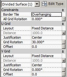
You can also change the background grid on the divided surface.  In this example one of the grids is rotated by 30 degrees:

The resulting patterns can be triangular or hexagonal in nature:
 Just by changing the size of the star (radius of underlying crcle) you can get radically different patterns.


I hope that someone finds a use for this flexible way to create parametric patterns in Revit (2013 or later).

Thursday, 1 August 2013

Scaling Revit Families Nested in Curtain Panel Patterns

Credits First

This post would not have happened without discussions at RTC or blog posts by the following people:
What I am showing here is a development of all those ideas, combined with a concept that I came up with for my RTC presentation "Fractal Fun with Revit Repeaters" earlier this year - more on that at a later date.

How to trim the edges of a pattern of repeated scaleable Revit families

The image on the left above shows a repeated pattern of complex shapes within a regular rectangular boundary - relatively easy to achieve in Revit!  On the right the boundary has been trimmed, and the pattern gets trimmed with it - not so easy.
Add in the ability to scale the pattern elements and it gets a whole lot trickier. 

Kelvin Tam showed us how to nest a planting category family into another planting family and then nest again into a different category family - this allows us to use the ability of planting category to automatically scale any irregular shape without having to create complex formulas and controlling geometry (see link above).

David Light applied that technique to nesting planting categories into curtain wall panels to create arrays of scaleable science fiction monsters marching across the landscape.

Andy Milburn applied the same technique to creating Musharabiya screens out of curtain walls.  He noted that there was a limitation of not being able to trim the edges of the pattern because curtain wall panels won't be be cut.

To solve that problem I used Marcello Sgambelluri's technique of questioning which similar category or situation does Revit allow you to do what you want?  In this case I knew from my RTC presentation "Fractal Fun" research that Revit will cut the edges of curtain wall panel pattern families when applied to divided surfaces.  So we should be able to apply that principle here - the only limitation being that it must be done in the conceptual modelling or adaptive component environment.

Here is how to do it:
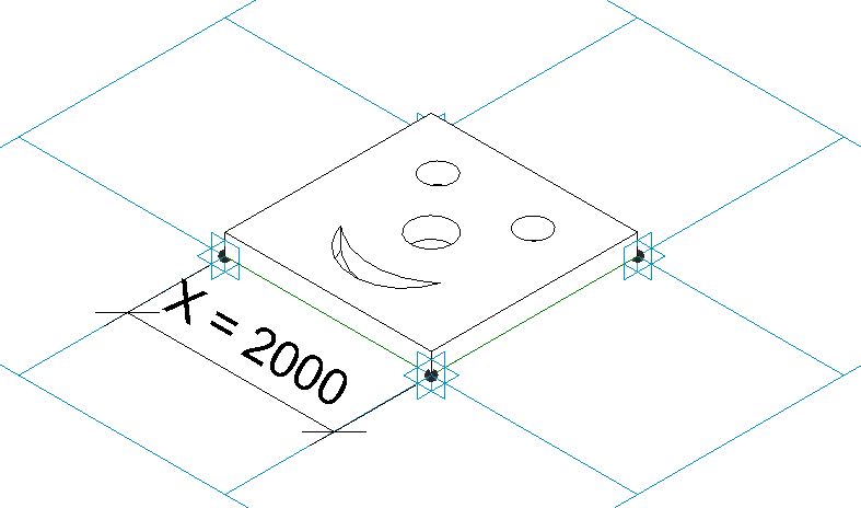
  • First start a new planting category family and create the desired pattern element within it - in this case a simple smiling face within a square (but it could be a complex geometric design).
  • Then start another new planting category family;
  • Load the first family into the second;  this is to make use of Revit's capability of automatically scaling plants and trees - it only works with nested families;
  • Start a new "Curtain Panel Pattern Based" family;
  • Place a dimension between two adjacent points; 
  • Make the dimension an instance reporting parameter 


  • Load the second planting family into it, and place it on the pattern.  You may need to devise a way to control the location of the component by hosting it on specific points
  • Select the planting family and link its "Height" parameter to the new reporting parameter in the pattern family;  you may need to add a formula to scale it up or down to match the size of the pattern grid (depending on the original family size) 
 

  • Create a new mass family or In-Place mass within a project;
  • create an irregular shaped form (can be a flat surface or an extruded shape);
  • Select a surface and divide it
  • Make sure the divided surface pattern is square and orthogonal - you may need to rotate the grid or set the spacing to fixed distance;
 
  • Load the curtain panel pattern family into the mass
  • Select the divided surface and change its type to the pattern family - it should automatically trim the pattern elements around the edges
  • NB. I think this did not work in the first version of the new conceptual massing in v2010?  but it seems to have been changed at some point since.
 
  • Depending on the grid spacing and location, Revit sometimes misses out small pieces or fails to trim elements that are hanging over the edge by only a small amount.

  • Occasionally it gets it quite wrong - in this example it was an in-place mass, which looked ok until the mass was "finished".


All this was done without tricky formulas - just by using the tools that Revit developers gave us, albeit not in ways that they expected us to use them.  There are obvious limitations of not being able to apply this to a normal curtain wall, so you have to use the massing tools to create a divided surface.

Obviously you aren't going to make smiley face patterns, but you should be able to apply these principles to real architectural design solutions.

Sunday, 28 July 2013

Revit Scaleable Spline Tree Family

Having returned from RTC in Vancouver a couple of weeks ago, I decided to put into practice some of the things that I learnt at the conference.  It was another great Revit conference in a fabulous location - Vancouver is a beautiful city, and the waterfront has been really well designed and carried out.  Aside from catching up with friends, I met lots of interesting people and attended plenty of good classes.  Although I attended Marcello Sgambelluri's class on scaling families at RTC in Auckland, it was also a big talking point in Vancouver.  I asked several people if they had attended the class, and many enthusiastic people had;  some others said that they did not want to see how to scale a Revit cow or elephant - well they missed out on a treat, because we learned many tricks that could be applied to totally different areas of Revit. 

Here is one idea that I have developed based on one of the methods that Marcello used to scale classical column families:
Marcello Sgambelluri - Scaling Classical Order of Columns

Scale By Spline

This concept has also been explored by others, notably
Andy Milburn - Spline Sailing

but I first need to describe the concept here. 

A spline can be scaled just by dragging one of its end points.  To control this within a scaleable Revit family, you need to lock or attach the end points of the spline to something that you can dimension.  Although you can dimension the end points directly, it is better to use something like a reference plane.  Here is a simple rig to demonstrate this process:
The vertical reference planes and width parameter will be used to control the distance between start and end of the spline, and in turn its scale.
The offset reference plane and parameter are required in order to control the location of the spline.
Once the rig is set up, draw a spline between the two top reference plane intersections

Use the align tool to lock the ends to the reference planes, in both directions (4 locks required)

Change the width parameter to check that the spline is locked to the vertical reference planes and that it scales properly.
Change the Offset parameter to check that the spline is locked to the horizontal reference plane.

This example establishes the principle of being able to control scaling and location of splines using reference planes.  The spline end points do not need to be orthogonal to each other - they can also be at an angle.

Revit Scaleable Spline Tree Family

We can now apply this principle to multiple splines linked to each other, to create a simple tree family.  This example is proof of concept, and is only done in 2D, but it could be applied to 3D trees.

First make a rig of reference planes that are controlled by parameters
Then draw a series of splines between each reference plane intersection.
Lock the ends of the splines to the intersections using the Align tool (and then padlock)
Try flexing the overall height parameter - this will not only change the overall height, but it will not affect the other parameters.  So only parts of the tree will scale, and others will not be affected depending on how the parameters are arranged.  In this example, the tree trunk is not affected by the change in height - only the top part of the tree scales.
Changing the intermediate parameters will alter the overall shape as well as the width
 Different tree forms can be achieved by playing around with the parameters
One tree family can be used to create multiple tree types that vary in shape and height
By adding a few more reference planes and splines it should be possible to create a family that has independant tree height and spread parameters.  And all this can be done without having to nest one planting family inside another - it works without nesting.

No doubt there will be people who say that this is not practicable, or that the trees look terrible - but this is only a proof of concept.  I'm hoping that it will give more ideas to others who can run with the concept and create wonderful flexible tree families.