BILT Speaker

BILT Speaker
RevitCat - Revit Consultant
Showing posts with label Divided surface. Show all posts

Saturday, 28 February 2015

RTC 2013 NA Competition Entry - More Revit Repeaters

Revit Museum of Innovation

Here is another image that was part of my drawing competition entry at RTC 2013 in Vancouver.  This is the outdoor view of the Revit Museum of Innovation - to go with the indoor image shown in this earlier blog post.  The image was created using 100% Revit - that means no Photoshop, no API, no Dynamo, no background jpegs.  The purpose of the image was to show what can be done using Repeaters in Revit - most of the techniques were described previously, with the exception of the conical sculpture and the background sky:

Conical Sculpture

There is a (hidden) half conical mass that has its surface divided. 
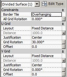
 The U grid is rotated by 30 degrees, which gives a spiral effect
 
On one of the nodes of the divided surface was placed one adaptive star component that changed its shape depending on how far it was from a specific reference point - that point being a second adaptive point snapped to an adjacent node on the spiral of the divided surface.

 When the adaptive star component is repeated, it replicates itself along the spiral path;  as it goes up the cone, the nodes become closer together and the star gradually changes shape until it becomes a hexagon, and then almost a circle.  This technique of using two circles with variable diameters to drive hosted geometry was described a couple of years ago - Revit Repeaters and Flexing Star Adaptive Components
Of course the cone itself had parameters to control its height and proportions, which in turn changed the patterns applied to its surface.

Background Sky

Notice the colour/lighting gradient in the background - it changes horizontally.
Originally I was trying to use the View Background settings to create a gradient between sky and horizon

The sky effect looked ok on screen, and when I did a screen capture:
The screen resolution and captured image were not good enough to project on a screen at RTC or to print out at A3.
But as soon as I tried to print it or export a jpeg image, it created a banded effect - this was in Revit 2013 at the time.   This bug was subsequently fixed in v2014.

At the time I had to make do with the buggy version 2013, so I resorted to an old technique for creating sky gradients:
I created a giant blue cylinder around the model, so that the viewpoint could see the inside of the cylinder as a background - as seen in the final artwork shown at the top.

For more about Revit Repeaters, refer to the Repeaters Index page

Thursday, 28 November 2013

Geometric Patterns from Parametric Revit Stars

In my previous post I showed how to make a parametric star in Revit - one that has a variable number of points.  Here are some examples of how that might be used in a parametric pattern.  I have shown something a little like this previously and also in my RTC 2012 presentation, but that was done using a fixed number of points in the star, although it changed shaped parametrically.

Repeater Star Patterns in Revit

Since the parametric stars are made as adaptive components, they can be placed on a node of a divided surface (in a conceptual mass or another adaptive component)
Once the star has been placed it can be arrayed using the "Repeater" command to form a geometric pattern
 
By changing the radius of the circular rig in the adaptive star, it changes the size of the star and hence the pattern
  Once the stars overlap it gives a completely different effect

 
Going back to the original size, the number of points on the star can be changed.  however, a five pointed star does not result in an interesting pattern once they overlap each other.  Likewise, 4 or 3 pointed stars don't look good (crosses and triangles)
Increasing the number of points to seven, does work reasonably well, although it looks a bit messy as the overlap increases!


 An eight point star works well on a square grid pattern:


You can also change the background grid on the divided surface.  In this example one of the grids is rotated by 30 degrees:

The resulting patterns can be triangular or hexagonal in nature:
 Just by changing the size of the star (radius of underlying crcle) you can get radically different patterns.


I hope that someone finds a use for this flexible way to create parametric patterns in Revit (2013 or later).

Thursday, 17 October 2013

How to Schedule Panel Locations on a Flat Rectangular Surface in Revit


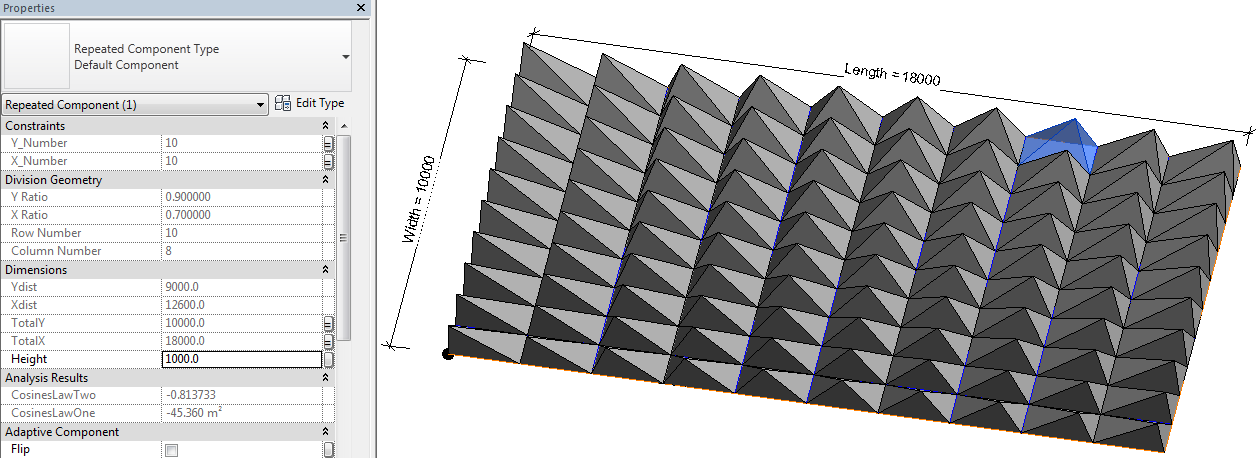
This post demonstrates how it is possible to schedule repeater component cell numbers on an orthogonal pattern within the Revit Conceptual Massing or Adaptive Component environment:

To set this up, first you need a rectangular surface, which has been divided; then you need to place an adaptive component onto the node(s) of the surface; once arrayed in two directions using the repeater function you can schedule the cell (column and row) numbers on the divided surface.  Of course it isn't that simple - the adaptive component has to be aware of its location relative to a fixed point, by doing some calculations:
  • The example here is perhaps a little more complicated than it needs be to demonstrate the principle, but it does a few other fun things too.
  • The adaptive component to be repeated must be set to “Shared” so it can be scheduled;  it needs to use shared parameters so they can be scheduled too.
  • In this case it is a 5 point adaptive – one for each corner of the base of a rectangle placed on each cell of the divided surface;  the fifth point works as a “Reactor” – it tracks the distance of the component from a base point.
  • This rectangle is made more interesting by having a pyramid on top that has an apex that moves depending where it is in the repeater pattern.
To create the adaptive component:
1.  Start a new generic adaptive family.
  • Place four points in a rectangular shape;  make them adaptive
  • Join the four points with reference lines (make sure 3D snapping is on)
2.  Set up the geometry for the pyramid (optional):
  • Place a point on each line  (if correctly hosted it displays as a small point)
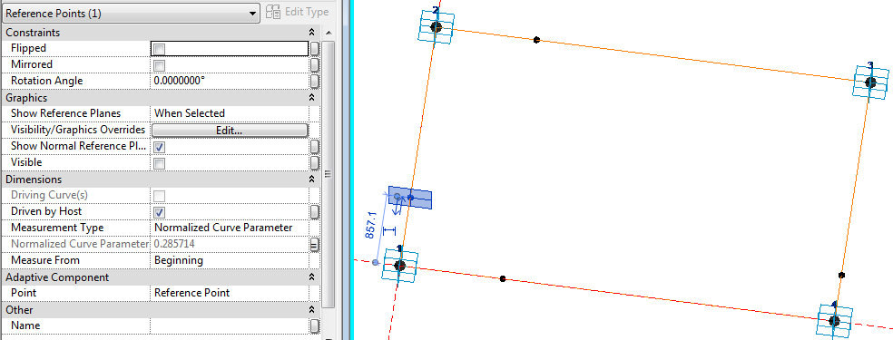
  • For each point assign a (Shared) parameter to its “Normalised Curve Parameter” – for the notional Y axis point, make it “Y_Ratio”;  its point on the opposite side will have its “Measure From” value set to End, rather than beginning, so that they line up.
  • Assign a parameter “X_Ratio” to the notional X axis points (one from beginning, one from end, depending on which direction you drew the reference lines)

  • Join the two opposing points with reference lines
  • Place another point on one of the linking reference lines
  • Select the point and the option bar should show:
 

  • Click on “Host by Intersection”, then select the opposing reference line;  it should move to the intersection of the reference lines
  • Set the “Show Reference Planes” property of the point to Always.
  • Set the work plane to the horizontal plane of the hosted intersection point (it only shows as a single line)
  • Place another point on top of the one on the intersection (ensure 3D snapping is on);  ignore the error message about duplicate points;
  • Select the new point and drag it up in the zed axis – its ”Offset” property should change.  If you are lucky, it should be a positive value (if it is zero, then the workplane or hosting went wrong);
  • Assign a “Height” parameter to it – if it was a negative value you’ll need to assign an interim parameter then convert it to positive with a formula, for the end user to understand.
  • This point becomes the apex of the pyramid;  
  • Join the point to the four corners of the base with four reference lines;
  • Flex the X_Ratio and Y_Ratio and Height parameters
  • Create a Form (surface) on each of the four sides of the pyramid
3.  Setting up the “Reactor” controls (Important):
  • Place a fifth adaptive point to the left of point 1 (bottom left corner of rectangle)
  • Use a reference line to join it to point 1
  • Join points 5 and 4 (Bottom right corner of rectangle) with another reference line – to create a triangle of lines.
  • Place 3 dimensions between the adaptive points 5 & 1, 1 &4, 4 & 5 – for each one make sure to set the relevant reference line as the work plane for the dimension;  it is vital to snap the dimensions to the adaptive points, rather than to line ends, surface corners etc (if not then you can’t use the dimensions later on in formulas)
  • Make each dimension as a reporting instance parameter, for use in the “cosine law” in trigonometry.  We need to calculate the angle in the triangle
  • The Cosine Law for calculating an angle when 3 sides are known, is:
    Angle γ = Arcos( (A² + B² - C²) / 2AB)
  • Revit version of Cosines formula:
    Angle γ = Acos( (A^2 + B^2 - C^2) / 2*A*B)


  • To work out the X and Y components of the distance “A” between points 5 and 1, use trigonometry:

  • This calculation assumes that the angle of the line between P1 and P4 is orthogonal – so it only works with a rectangular repeater pattern.
4.  Calculation of column and row numbers:
  • This requires knowledge of how many rows/columns there will be in the repeater, and the overall size of the repeater


  • Parameters for these need to be built in to the component as shared parameters (for scheduling), as shown below;  these can subsequently be linked to the parent family parameters for these values.
    X Number and Y Number should be integers (count of repeats in each direction)
    Column Number and Row Number should also be integers.
    X Ratio and Y Ratio should be number parameters
  • You may need a couple of checks to take care of when it has zero values for the distances.

5.  Creation of the repeater:
  • The pyramid family needs to be loaded into another family that can support a divided surface – this could be an adaptive component, a mass family or an in-place mass family in a project.  In this example it will be an in-place mass family.
  • Load the pyramid into the project
  • Start an in-place mass family
  • Draw a rectangle of reference lines,
  • Give the rectangle dimension parameters of Length and Width
  • Generate a form (surface) from the lines
  • Select the surface and Divide Surface 
  • Make the nodes visible on the surface (Surface representation)
  • Assign parameters to U Number and V Number on the surface
  • Place a point just to the left of the bottom left corner of the surface – this will become the control point for measuring distance.  It is important for getting the “Reactor” effect working.
  • Place an instance of the pyramid component by snapping the first four placement points onto four adjacent nodes in the same order as you originally created the adaptive points (say clockwise);  place the fifth point on the external point – it is vital that it does not go onto a node of the surface

  • Link 4 parameters to equivalent parent parameters:
    Y_Number to     V Number
    X_Number to     U Number
    TotalX  to  Length
    TotalY  to  Width
  • Hide the nodes on the surface (Using Surface Representation - they cannot be controlled by any view settings)
  • Select the free control point and move it very close to the bottom left corner of the surface.
  • Select the Pyramid and turn it into a repeater 
  • All being well, the pyramid will array itself over the whole surface, but each instance will look slightly different as the apex point is changed depending on its distance from the control point in the bottom left corner.  If not, it could be caused by a problem with the component itself, or else the fifth adaptive point might be hosted on the same point as adaptive point one, in which case it would move with it.
  • Select (tab) any one of the pyramids;  it should display properties including its correct column and row number

  • Finish the in-place mass family
6.  Create a generic Schedule:
  • Add the column and row numbers, and any other parameters you require
  • You will be able to edit the values for Comments and Mark, but no other instance values
  • If you edit the mass family, it allows you to manually select any of the components in the repeater.  Then you can set it to “No Component” or to any other 5 point adaptive component.
When you edit the mass family, the schedule temporarily goes blank.  Sadly this means that it is not possible to drive the geometry from the schedule.  However, it does make it easier to identify and label components in a schedule – useful for adding and editing Mark values to match column and row numbers.

This technique will not work with a curved surface because it all works by calculating the actual distance from the control point to the BL corner of the pyramid and relating that to the overall length of the surface.  It will only work on an orthogonal divided surface, unless you are a mathematical genius and can write formulas to handle more complex geometry!