BILT Speaker

BILT Speaker
RevitCat - Revit Consultant
Showing posts with label adaptive point. Show all posts

Sunday, 6 April 2014

Adaptive Component Origins in Revit

Have you ever wondered how Revit manages the "Origin" (X,Y,Z = 0,0,0) of an adaptive component?
It is somewhat different from the way it handles origins and insertion points of traditional Revit families.  So here is an analysis of the differences between the two.

Traditional Family Insertion Points

A traditional Revit family typically has three reference planes that intersect at the origin point - representing the X, Y and Z axes.  To start with, the origin is the same as the insertion point when the component is placed in a model.  For this discussion we will only think about the X and Y axes in plan because the vertical insertion point (in Z axis) is locked to the level (in the family) and does not change (unless you use the Offset property - see below).
At some point those X and Y reference planes might be moved within the family.  This may or may not affect the insertion point, depending on the reference plane properties:
  • If the reference planes are moved, and they are set to "Defines Origin" then the insertion point will move to the intersection of the two reference planes
  • Alternatively, one or two other reference planes might be set to "Defines Origin" - if they are in the X or Y axis, they will take over the origin property from the Centre reference planes (and the centre reference planes will have that property unchecked);  if the other reference plans are not orthogonal then Revit will ignore that setting, and use the centre reference planes or the original origin point.
  • If no reference planes in the family are set to "Defines Origin" then the insertion point will remain at the original X=0, Y=0 origin
  • If only one of the reference planes is set to "Defines Origin" then the insertion point will be at the intersection of the "Defines Origin" reference plane and the original perpendicular axis.
  • If the insertion point of a family is changed and then reloaded into a project  where some have previously been placed, it will overwrite the family definition in the project and will move the geometry in any placed components of that family (by the same amount that the insertion point moved).
For this reason it is good practise to make sure the two reference planes that define the insertion point are not moved from the origin once you have decided where it needs to be (keep them pinned).  Geometry should be moved relative to the origin if need be.

Hot Tip:  If you lose track of the true origin, just create an Autocad file with a cross intersecting at X=0, Y=0.  Save the dwg and import it in to your family at "Origin to Origin"; trace over the cross with reference planes or lines; delete the dwg; purge the dwg (since you can't link dwgs into a family, you need to import, then purge).

Offset.
Most traditional unhosted Revit families have an "Offset" system parameter that is automatically created when you load the family into a project (this contols the Z offset from the placement level or workplane).  Recently we found some old plumbing families (baths) that did not have the Offset parameter - we believe that this is because they were created from very old family templates that pre-date the addition of this offset capability, from the dim distant Revit past.  Hosted and face-based families usually have an "Elevation" system parameter (rather than Offset), which works like Offset but only in the project vertical axis, whereas the Offset parameter works in the local z axis of the family, which may not be vertical in the project.

Adaptive Family Insertion Points

Adaptive components behave in a different way.:
  • Although they have a true origin with two reference planes intersecting there, the insertion point can be overridden by adaptive points.
  • If there is no adaptive point in the family then it behaves almost like a traditional family, except that the "Defines Origin" parameters appear to make no difference - the origin and insertion point remains at 0,0 regardless of whether any reference planes have that property checked
  • If there is an adaptive Placement Point in the family, then Revit uses that as the insertion point of the family;  however it still remembers the true origin
 
  • If the only adaptive points in the family are Shape Handle points, then Revit uses the traditional origin as the insertion point (not the adaptive point)
  • If a placement adaptive point is deleted (in the family) or changed to a shape handle point, Revit does not move the geometry when the family is reloaded into a project.  This is because Revit knows and remembers where the origin is even though it uses adaptive placement points for insertion - this is logical but can get confusing.
If a placement adaptive point is moved (in the family) then reloaded into a project it might move geometry of previously placed components - it depends if the geometry is hosted on the adaptive point or not.   In this example the hexagon is hosted on the adaptive point;  the circles are just placed on the level workplane, close to the origin point.
Geometry in the family
Geometry in the model
  • Any geometry hosted on the adaptive point remains where it was in the model when the family is reloaded; 
  • Any geometry placed in the  family but not hosted on an adaptive point will move relative to the 0,0 origin point - so if the adaptive point is moved/flexed in the family it will end up a different distance from the point in the family;  when reloaded, the unhosted geometry will move in the project so that it retains that distance, while the hosted geometry remains put at the insertion point
 
  • Once you are in the project environment, and you move the adaptive point, something different again happens:  all the geometry in the family moves together! (this can be hellishly confusing).
Offset
Adaptive components do not have an Offset system parameter.  Instead they have an "Elevation" parameter, which does not appear to do anything - neither unhosted elements nor elements hosted on adaptive points will move when this Elevation value is altered.

Adaptive Component Reference Planes

Most adaptive component demos that I have seen show the placement of adaptive points in random locations in the family.  Why?  Probably just because you can.
I am more careful - I always put adaptive point #1 at the origin (intersection of the two reference planes that exist in the family template).  I do it for a reason, even though it takes a few extra steps - I have to go to a plan view because points won't snap to ref plane intersections in 3D.  If there is a second adaptive point I will snap it to the X axis for the same reason:  . . . .
  • Let us assume that you place an adaptive point in a random location;
  • Make it adaptive
  • Then place some geometry associated with the point (set the work plane to its horizontal plane first)
  •  You could place a dimension just to check how far it is from the origin
  • Load the adaptive family into a project and place one (it uses the adaptive point for insertion)
  • Try placing a dimension to roughly the same distance from the adaptive point as it was in the family - the hidden reference plane in the family will highlight and allow you to snap to it
  •  Once you place the dimension, the highlighted reference plane disappears
  • You could do the same with the other axis reference plane
  • Revit will attempt to snap to those reference planes and their intersections during many other commands that involve snapping - even to remote objects.
Its not very helpful is it?  In fact it is downright annoying when you have lots of adaptive components placed.
  • Imagine what happens when you have two adaptive points placed in the family at random, with some geometry between them?  

  • The hidden reference planes are now at crazy angles in the project and cause all kinds of random snapping locations

Hot Tip:  In v2013 the developers gave us a solution to this issue by enabling the  properties of those reference planes to be set to "Not a Reference" [that did not work in v2012, I think]
Good Practise: 
  1. Chances are that you will forget to change this setting some time, so it is a good idea to get into the habit of putting adaptive point #1 at the true origin, and point #2 on the X axis so that these reference planes will be orthogonal to the geometry.
  2. Whenever you flex the family by moving the adaptive points, remember to put them back to where they were, so that you don't get strange behaviour where unhosted elements in the family might move in the model when you reload the family into the project.

For more differences between traditional and adaptive families refer to Rival Revit Environments

Sunday, 3 November 2013

Circular repeater geometry in Revit

In previous posts I have described how easy it is in Revit to use a circle as a rig to host regular geometric shapes like squares and hexagons.  It occurred to me the other day that circles would also be ideal hosts for parametric stars;  put that together with Repeaters and you get some interesting possibilities . . .

Here is how to create a parametric star:
  • Create a new adaptive component;  
  • Place a point at the origin; make its reference planes visible
  • Set the horizontal ref plane as the work plane
  • Place a reference line circle onto the point
  • Make its radius dimension into a parameter
  • Select the circle
  • Divide Path
  •  It will create a divided path on top of the circle with 6 nodes
  • Create another Adaptive component
  • Place two points, and make them adaptive
  • Place a line between the points, remembering to enable "3D Snapping" first
  • Save the second family (eg. as "AC 2pt Line")
  • Load it into the first family
  • Place one of the components onto two non-adjacent nodes
 
  • Select the two-point component and click on the Repeat command
  • You should end up with a triangle
  • NB.  if you placed the two-point adaptive line component onto adjacent nodes you'd get a hexagon
  • Actually, a triangle is only half of what we want, but we need to backtrack to get the correct result - so, UNDO the repeat command
  • Place a second two-point adaptive on alternating non-adjacent nodes
  •  Select both lines and click on Repeat
  •   
  •  You should end up with a six pointed star, which is now a "Repeater"
  • Select the divided path, and change the number of nodes to 5, giving you a five pointed star
  •  Change it to 4, which gives a cross (not so useful)
  •  Change it to 3 for a triangle
  •  Change it back up to 7
  •  And then to 8 - this gives an eight pointed star that could be useful in tiling patterns when repeated itself on a divided surface
  •  As the number of nodes increase, the shape becomes closer to a circle
  • Now all you need to do is turn the number of nodes into a parameter to get yourself a one-point adaptive parametric star component
  • Oh, one more thing - you need to make the nodes of the divided path not visible otherwise they will show up when this component is placed in a project or another family


How useful is this going to be?  We'll investigate that in a future post . . .
Here is one possible use - geometric patterns


Thursday, 17 October 2013

How to Schedule Panel Locations on a Flat Rectangular Surface in Revit


This post demonstrates how it is possible to schedule repeater component cell numbers on an orthogonal pattern within the Revit Conceptual Massing or Adaptive Component environment:

To set this up, first you need a rectangular surface, which has been divided; then you need to place an adaptive component onto the node(s) of the surface; once arrayed in two directions using the repeater function you can schedule the cell (column and row) numbers on the divided surface.  Of course it isn't that simple - the adaptive component has to be aware of its location relative to a fixed point, by doing some calculations:
  • The example here is perhaps a little more complicated than it needs be to demonstrate the principle, but it does a few other fun things too.
  • The adaptive component to be repeated must be set to “Shared” so it can be scheduled;  it needs to use shared parameters so they can be scheduled too.
  • In this case it is a 5 point adaptive – one for each corner of the base of a rectangle placed on each cell of the divided surface;  the fifth point works as a “Reactor” – it tracks the distance of the component from a base point.
  • This rectangle is made more interesting by having a pyramid on top that has an apex that moves depending where it is in the repeater pattern.
To create the adaptive component:
1.  Start a new generic adaptive family.
  • Place four points in a rectangular shape;  make them adaptive
  • Join the four points with reference lines (make sure 3D snapping is on)
2.  Set up the geometry for the pyramid (optional):
  • Place a point on each line  (if correctly hosted it displays as a small point)
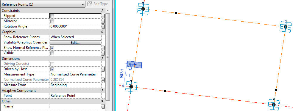
  • For each point assign a (Shared) parameter to its “Normalised Curve Parameter” – for the notional Y axis point, make it “Y_Ratio”;  its point on the opposite side will have its “Measure From” value set to End, rather than beginning, so that they line up.
  • Assign a parameter “X_Ratio” to the notional X axis points (one from beginning, one from end, depending on which direction you drew the reference lines)

  • Join the two opposing points with reference lines
  • Place another point on one of the linking reference lines
  • Select the point and the option bar should show:
 

  • Click on “Host by Intersection”, then select the opposing reference line;  it should move to the intersection of the reference lines
  • Set the “Show Reference Planes” property of the point to Always.
  • Set the work plane to the horizontal plane of the hosted intersection point (it only shows as a single line)
  • Place another point on top of the one on the intersection (ensure 3D snapping is on);  ignore the error message about duplicate points;
  • Select the new point and drag it up in the zed axis – its ”Offset” property should change.  If you are lucky, it should be a positive value (if it is zero, then the workplane or hosting went wrong);
  • Assign a “Height” parameter to it – if it was a negative value you’ll need to assign an interim parameter then convert it to positive with a formula, for the end user to understand.
  • This point becomes the apex of the pyramid;  
  • Join the point to the four corners of the base with four reference lines;
  • Flex the X_Ratio and Y_Ratio and Height parameters
  • Create a Form (surface) on each of the four sides of the pyramid
3.  Setting up the “Reactor” controls (Important):
  • Place a fifth adaptive point to the left of point 1 (bottom left corner of rectangle)
  • Use a reference line to join it to point 1
  • Join points 5 and 4 (Bottom right corner of rectangle) with another reference line – to create a triangle of lines.
  • Place 3 dimensions between the adaptive points 5 & 1, 1 &4, 4 & 5 – for each one make sure to set the relevant reference line as the work plane for the dimension;  it is vital to snap the dimensions to the adaptive points, rather than to line ends, surface corners etc (if not then you can’t use the dimensions later on in formulas)
  • Make each dimension as a reporting instance parameter, for use in the “cosine law” in trigonometry.  We need to calculate the angle in the triangle
  • The Cosine Law for calculating an angle when 3 sides are known, is:
    Angle γ = Arcos( (A² + B² - C²) / 2AB)
  • Revit version of Cosines formula:
    Angle γ = Acos( (A^2 + B^2 - C^2) / 2*A*B)


  • To work out the X and Y components of the distance “A” between points 5 and 1, use trigonometry:

  • This calculation assumes that the angle of the line between P1 and P4 is orthogonal – so it only works with a rectangular repeater pattern.
4.  Calculation of column and row numbers:
  • This requires knowledge of how many rows/columns there will be in the repeater, and the overall size of the repeater


  • Parameters for these need to be built in to the component as shared parameters (for scheduling), as shown below;  these can subsequently be linked to the parent family parameters for these values.
    X Number and Y Number should be integers (count of repeats in each direction)
    Column Number and Row Number should also be integers.
    X Ratio and Y Ratio should be number parameters
  • You may need a couple of checks to take care of when it has zero values for the distances.

5.  Creation of the repeater:
  • The pyramid family needs to be loaded into another family that can support a divided surface – this could be an adaptive component, a mass family or an in-place mass family in a project.  In this example it will be an in-place mass family.
  • Load the pyramid into the project
  • Start an in-place mass family
  • Draw a rectangle of reference lines,
  • Give the rectangle dimension parameters of Length and Width
  • Generate a form (surface) from the lines
  • Select the surface and Divide Surface 
  • Make the nodes visible on the surface (Surface representation)
  • Assign parameters to U Number and V Number on the surface
  • Place a point just to the left of the bottom left corner of the surface – this will become the control point for measuring distance.  It is important for getting the “Reactor” effect working.
  • Place an instance of the pyramid component by snapping the first four placement points onto four adjacent nodes in the same order as you originally created the adaptive points (say clockwise);  place the fifth point on the external point – it is vital that it does not go onto a node of the surface

  • Link 4 parameters to equivalent parent parameters:
    Y_Number to     V Number
    X_Number to     U Number
    TotalX  to  Length
    TotalY  to  Width
  • Hide the nodes on the surface (Using Surface Representation - they cannot be controlled by any view settings)
  • Select the free control point and move it very close to the bottom left corner of the surface.
  • Select the Pyramid and turn it into a repeater 
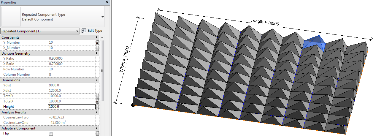
  • All being well, the pyramid will array itself over the whole surface, but each instance will look slightly different as the apex point is changed depending on its distance from the control point in the bottom left corner.  If not, it could be caused by a problem with the component itself, or else the fifth adaptive point might be hosted on the same point as adaptive point one, in which case it would move with it.
  • Select (tab) any one of the pyramids;  it should display properties including its correct column and row number

  • Finish the in-place mass family
6.  Create a generic Schedule:
  • Add the column and row numbers, and any other parameters you require
  • You will be able to edit the values for Comments and Mark, but no other instance values
  • If you edit the mass family, it allows you to manually select any of the components in the repeater.  Then you can set it to “No Component” or to any other 5 point adaptive component.
When you edit the mass family, the schedule temporarily goes blank.  Sadly this means that it is not possible to drive the geometry from the schedule.  However, it does make it easier to identify and label components in a schedule – useful for adding and editing Mark values to match column and row numbers.

This technique will not work with a curved surface because it all works by calculating the actual distance from the control point to the BL corner of the pyramid and relating that to the overall length of the surface.  It will only work on an orthogonal divided surface, unless you are a mathematical genius and can write formulas to handle more complex geometry!