BILT Speaker

BILT Speaker
RevitCat - Revit Consultant
Showing posts with label rig. Show all posts

Wednesday, 8 February 2017

Gare do Oriente - Nested Revit Repeaters - part 2


Following on from my previous post about modelling the roof of Santiago Calatrava's Gare do Oriente railway station roof, here is part 2:

Placing roof panels on the top of the supporting column

The process is described on a YouTube video, so I will only summarise steps below.
YouTube link here


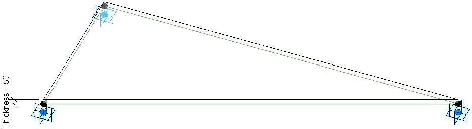
1. Create an adaptive Roof Panel

  • Start a new Adaptive generic family
  • Place 3 points (anywhere)
  • Make them all adaptive
  • (Optional) If you want to raise the panel above the structure, host an additional point on each adaptive point;  move it up and associate its Offset to a parameter called Panel Offset
  • Join the three adaptive points (or offset points) with reference lines (making sure 3D snapping is on)
  • Select the reference lines
  • Create form; give the panel a thickness if desired
  • Associate the form's material to a parameter
  • Save the family with a name such as 'AC 3pt Roof Panel'.  I like to use a prefix code in the name to indicate it is adaptive (AC) and the number of placement points (3pt).
Place a Roof Panel

  • Load the roof panel family into the support rig family created in part 1
  • Place an adaptive roof panel component onto the rig:
  • First placement point, snap to the lowest hosted point on the vertical line of the rig
  • Second, snap to a point on the lower circle
  • Third, snap to a point on the upper circle, one point around from the lower circle snap (anticlockwise, depending on the point order in your panel)

Repeater

  • Try selecting the panel and turn it into a 'repeater'
  • The panel will be repeated around every point (8 times) - not the result we desire !

  • Undo the repeater - we have to 'teach' Revit how the pattern should be repeated:
  • Place a second panel in the same relative location but two points along the circle - it is very important that you place the points in exactly the same order as the first panel, making sure that you snap to the points on the rig, not on the panel that you have already placed.
  • Select both panels and repeat them
  • This time it should place a panel in every quadrant
  • To complete the other half, place a panel in one of the gaps
  • Then place another in the next gap - to establish the repeat pattern spacing
  • Select them both and 'Repeat'
  • Now we should get the correct pattern of two alternating repeaters of four panels each

The roof panels on top of the support rig are now complete - and should look square in plan, with valleys from the perimeter sloping in to the centre.  Flex any of the parameters in the rig and the panels should all move with it.

The next steps:
Step 3 - Creating the structural elements and placing on the rig
Step 4  Adding Struts to the structure
Step 5  Assembling the Array of Structural Columns
For more detail, refer to an earlier post I did on Adaptive swept blends

Wednesday, 1 February 2017

Gare do Oriente - Nested Revit Repeaters - part 1

In 2013 I presented a paper titled "Fractal Fun with Revit Repeaters and Adaptive Components" at three RTC events in Auckland, Vancouver and at the inaugural European Revit conference in Delft, in the Netherlands.  Part of the presentation involved a live demonstration of how to construct a parametric Revit model of the roof of the Gare do Oriente railway station in Lisbon, designed by Santiago Calatrava.

Gare do Oriente by Santiago Calatrava

Since then I have had a number of people asking me how it was done - it was of course described in step-by-step detail in the RTC handouts.  Those are not so easily accessible now, so I am posting the content here, in stages.  Part 1 involves creating a rig for one of the structural supports of the roof.


I will not show a step-by-step guide here as the process is described in a video tutorial:
here is a youtube link


As a reminder, below is a list of the steps required in the process:

  • Start a new Adaptive Component
  • Place a point at the origin (X,Y,Z = 0)
  • Make it adaptive
  • Make its 'Show reference planes' property to 'Always' visible
  • Set the workplane as the horizontal reference plane of the adaptive point
  • Place another point on top of the adaptive point
  • Move it up in the Z direction
  • Associate its 'Offset' property to a parameter 'Height' (NB. it will only have an Offset property if it is correctly hosted on the horizontal reference plane of the adaptive point)
  • Draw a reference line from the top point down to the adaptive point, making sure 3D snapping is on (Options toolbar)
  • Place two more points, both hosted on the reference line
  • Make the upper line-hosted point always show reference planes
  • Change its Measurement Type to 'Chord Length' or 'Segment Length' (NB. because the host is a straight line, in this case Segment length is the same as chord length, which just means direct distance)
Hosted point Measurement Type
  • Associate its 'Chord length' to a parameter called 'Perimeter Drop'
  • Change the Measurement Type of the lower hosted point to 'Chord Length' or 'Segment Length'
  • Associate its 'Chord length' property to a parameter called 'Valley Drop'
  • Flex the parameters to test the rig thus far;  move the adaptive point to check everything else is hosted to it
Circles to host geometry
  • Set the workplane as the horizontal reference plane of the top point
  • Place a reference circle centred on the point
  • Make its temporary radius dimension into an actual dimension
  • Associate the radius dimension to a parameter called 'Radius outside'
  • Set the workplane as the reference plane of the upper hosted point
  • Place a reference circle centred on the point
  • Make its temporary radius dimension into an actual dimension
  • Associate the radius dimension to a parameter called 'Radius inside'
  • Create a formula for 'Radius outside' = Radius inside * 1.4142
Divide Path
  • Select the top circle
  • Click on the 'Divide Path' icon
  • Set the number of points to 8
  • Select the lower circle
  • Click on the 'Divide Path' icon
  • Set the number of points to 8
The basic rig is now complete, ready for adaptive components and repeaters to be hosted on it.  These will be covered in following tutorials.

Step 5  Assembling the Array of Structural Columns

Sunday, 3 November 2013

Circular repeater geometry in Revit

In previous posts I have described how easy it is in Revit to use a circle as a rig to host regular geometric shapes like squares and hexagons.  It occurred to me the other day that circles would also be ideal hosts for parametric stars;  put that together with Repeaters and you get some interesting possibilities . . .

Here is how to create a parametric star:
  • Create a new adaptive component;  
  • Place a point at the origin; make its reference planes visible
  • Set the horizontal ref plane as the work plane
  • Place a reference line circle onto the point
  • Make its radius dimension into a parameter
  • Select the circle
  • Divide Path
  •  It will create a divided path on top of the circle with 6 nodes
  • Create another Adaptive component
  • Place two points, and make them adaptive
  • Place a line between the points, remembering to enable "3D Snapping" first
  • Save the second family (eg. as "AC 2pt Line")
  • Load it into the first family
  • Place one of the components onto two non-adjacent nodes
 
  • Select the two-point component and click on the Repeat command
  • You should end up with a triangle
  • NB.  if you placed the two-point adaptive line component onto adjacent nodes you'd get a hexagon
  • Actually, a triangle is only half of what we want, but we need to backtrack to get the correct result - so, UNDO the repeat command
  • Place a second two-point adaptive on alternating non-adjacent nodes
  •  Select both lines and click on Repeat
  •   
  •  You should end up with a six pointed star, which is now a "Repeater"
  • Select the divided path, and change the number of nodes to 5, giving you a five pointed star
  •  Change it to 4, which gives a cross (not so useful)
  •  Change it to 3 for a triangle
  •  Change it back up to 7
  •  And then to 8 - this gives an eight pointed star that could be useful in tiling patterns when repeated itself on a divided surface
  •  As the number of nodes increase, the shape becomes closer to a circle
  • Now all you need to do is turn the number of nodes into a parameter to get yourself a one-point adaptive parametric star component
  • Oh, one more thing - you need to make the nodes of the divided path not visible otherwise they will show up when this component is placed in a project or another family


How useful is this going to be?  We'll investigate that in a future post . . .
Here is one possible use - geometric patterns