Open your column structure adaptive family created in steps 1 - 4
Set the work plane as the horizontal reference plane of adaptive point 1
Place a reference polygon centred on the adaptive point, first making it 4 sided
It will give four temporary dimensions, one for each side, from the centreline references
Make these into real dimensions
Select all four dimensions and associate them to a parameter called 'Half base'
Optional: create a new parameter called Base Width
Optional: add a formula to 'Half base' = Base Width /2
Select the four reference lines of the polygon
Create form
Drag its top surface up, and it should enable a temporary dimension for the height
Turn that into a dimension
Associate it to a parameter 'Base Height'
The family is now ready to use in a project model
Create an Array of Columns
Load the family into a project
Create railway platforms (floors or extrusions of some kind)
Create an in-place Mass family
Draw a rectangle of reference lines, with the two long sides centred on the outside platforms
The length of the rectangle should be a multiple of the distance between each platform
Select the four reference lines (rectangle)
Create a form
Drag the top surface of the form up or down so that it is flush with the top of the platforms
Select the top surface of the form
Click on the 'Divide surface' icon
Depending on the number of platforms/tracks, and the length of the rectangle, adjust the number of U and V grid divisions to achieve a square pattern of grids, one per platform - remembering that the number matches the grid lines not the divisions
Change the surface representation of the divided path; make the Nodes visible
Place one of the structural adaptive components onto any one of the nodes
Select the component and click on the Repeater icon
It should create an array of columns, one on each node
Select the divided surface and hide its nodes again, so that they will not be visible in the project in any views. NB. if any divided path nodes are visible in the structure, you need to hide those back in the family and reload them (which can be painfully slow, so its better to do so before creating the repeater)
Finish the Mass family
In the project Browser, select the column family and change its 'Inside Radius' property to match half the spacing between nodes (platforms) - this should ensure that the overall size of the roof matches the divided surface grid size
Adjust any of its other properties as desired - eg. Base Height
The individual nested families will most likely be shared families, unless you changed that when creating them - so you should be able to adjust other parameters by selecting the nested families in the project browser - eg. Number of struts. NB. it can be slow to make those property changes depending on your computer, but remember that Revit is doing a lot of calculating for each change, and it is still much quicker than creating such a structure by conventional Revit modeling tools.
You should now have a basic parametric model of the railway station roof of Santiago Calatrava's Gare do Oriente in Lisbon
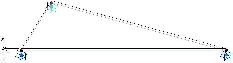
Join all three points with reference lines, ensuring that 3D snapping is ON
Add an arc between points 1 and 3; the arc must be kept planar with the 3 points, so it needs to be hosted to a rig (or alternatively a plane - not shown here)
Place a hosted point midway along the line between points 1 and 3
Place a reference line from that hosted point to adaptive point 2
Place another hosted point on that new line
Place a reference arc by Start-End-Radius, snapping to adaptive points 1, 3 and then to the latest hosted point
Create a curved swept blend along the arc:
Place two more hosted points close to each end of the arc
Create a new profile family from a generic adaptive template (not a traditional profile family template)
It does not require an adaptive point
Draw a 2D profile closed shape on the level work plane - in this example a T-shape
Dimension it and make it parametric
Save and load into the first adaptive family
Place a profile component onto each of the hosted points on the arc
NB. The reason for hosting the profiles onto points that are themselves hosted on the arc is that it gives much better control: The points have rotation parameters as well as parameters to control their distance along the arc - required to vary depending on the structural connections. Hosting the profiles directly on the arc would not give those controls.
Duplicate the type of the profile component closest to adaptive point 1
Make its dimensions larger
Select both profiles plus the reference arc
Create form
It will generate a swept blend that tapers to a smaller size towards point 3
On the rig, add a new hosted point onto the vertical reference line - this represents the springing point of the structure where it starts to curve out
Below this will be a rectangular extrusion, to be added later
This point will host the base of the structure adaptive components
Change its Measurement Type property to segment or chord length
Associate its segment/chord length to a parameter for Height of springing point
If you have the roof panels already in place on the rig (Step 2), it will probably be easier if you temporarily hide them before starting, to make snapping easier.
Place one of the support adaptive components, making sure to snap the 4 placement points onto the rig in the right order:
Springing point
Central valley hosted point on vertical line
Divided path point on inner circle (orthogonally, along X axis from origin)
Divided path point on outer circle, one division around anti-clockwise
Array a pattern around the circle using the Revit Repeater function:
If you select just the one structural element and repeat it, you get a straightforward radial pattern - this is not what we want (so, undo it)
We need to teach Revit how the array pattern should go - so you have to place a second structural component:
Place another adaptive component 90 degrees around the circle in the same sequence
The first two placement points go onto hosted points that are already occupied by the first structural component - so it is vital that you snap to the host points, and not to end points or adaptive points on the component.
Watch the prompt in the bottom left corner of the screen before each point placement - the first two should be to Point of Reference points
The second two should be onto Point of Divided path
Use this technique for every subsequent placement of adaptive points - it gets progressively more tricky as you go
Select the two adaptive structural components
Click on the Repeater icon
You should get the desired pattern if all adaptive points were hosted correctly.
If not you may be able to rehost the points (if you can guess which one is wrong!) - or just delete the adaptive component and place it again
The next step is to place two more structural components in the reverse direction (clockwise)
You could try placing them to the correct hosts, but it is really difficult with all those elements in the way - so it is easier to temporarily hide the repeater first
You may find that when you hide the repeater, the nested tubular components around the top do not hide. In which case, you need to select one, then right-click to select all instances and hide those too
Once placed, the two new structural components will fit in the gaps between the first repeater element
Some of the structural members will be in the same place as the original ones, so you may get a warning message about identical instances.
If this is an issue (for scheduling etc), then you will need to go back into the adaptive structural component and give the common elements a visibility instance parameter - back in the rig family, you can then switch off the duplicate structural members on the two newly placed components.
Select the two new components and array them using the Repeat function
Now the basic structure should be complete
Try flexing the parameters for the rig dimensions to check that the structure moves with it.
If you have the roof panels already placed, make them visible again to check that it aligns correctly
Placing roof panels on the top of the supporting column
The process is described on a YouTube video, so I will only summarise steps below. YouTube link here
1. Create an adaptive Roof Panel
Start a new Adaptive generic family
Place 3 points (anywhere)
Make them all adaptive
(Optional) If you want to raise the panel above the structure, host an additional point on each adaptive point; move it up and associate its Offset to a parameter called Panel Offset
Join the three adaptive points (or offset points) with reference lines (making sure 3D snapping is on)
Select the reference lines
Create form; give the panel a thickness if desired
Associate the form's material to a parameter
Save the family with a name such as 'AC 3pt Roof Panel'. I like to use a prefix code in the name to indicate it is adaptive (AC) and the number of placement points (3pt).
Place a Roof Panel
Load the roof panel family into the support rig family created in part 1
Place an adaptive roof panel component onto the rig:
First placement point, snap to the lowest hosted point on the vertical line of the rig
Second, snap to a point on the lower circle
Third, snap to a point on the upper circle, one point around from the lower circle snap (anticlockwise, depending on the point order in your panel)
Repeater
Try selecting the panel and turn it into a 'repeater'
The panel will be repeated around every point (8 times) - not the result we desire !
Undo the repeater - we have to 'teach' Revit how the pattern should be repeated:
Place a second panel in the same relative location but two points along the circle - it is very important that you place the points in exactly the same order as the first panel, making sure that you snap to the points on the rig, not on the panel that you have already placed.
Select both panels and repeat them
This time it should place a panel in every quadrant
To complete the other half, place a panel in one of the gaps
Then place another in the next gap - to establish the repeat pattern spacing
Select them both and 'Repeat'
Now we should get the correct pattern of two alternating repeaters of four panels each
The roof panels on top of the support rig are now complete - and should look square in plan, with valleys from the perimeter sloping in to the centre. Flex any of the parameters in the rig and the panels should all move with it.