BILT Speaker

BILT Speaker
RevitCat - Revit Consultant
Showing posts with label dimension. Show all posts

Monday, 23 September 2019

Inconsistent Units Settings UI in Revit


There are several very different ways of getting to Units Settings in the Revit User Interface.  Most of them are not very intuitive - and certainly they are totally different from each other.

Project Unit Settings

There are 3 different icons on the 'Manage' ribbon, depending on your screen resolution and size:

Largest resolution or screen
 If you are operating on a laptop or low resolution, the icon automatically reduces in size, and you may or may not get a text description:
Medium resolution or screen

Smallest resolution or screen

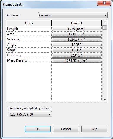
Once you click on the Project Units icon it takes you to the units dialog box, which has a list of different kinds of units:


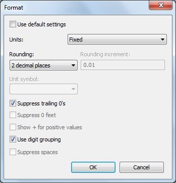
Once you choose a particular unit type, it gives the project-wide 'Format' settings for that type.  Since this is the project settings, the checkbox at the top is greyed out.   Some of the checkboxes are related only to imperial measurements so would always be greyed out for metric users.

This dialog box is the one common UI that appears for all methods of accessing units - but different items are greyed out in each situation that the dialog box appears.


Dimension Units

  • Select a Dimension in the project 
  • Click on Edit Type


  • Click on the Units Setting property
  • This takes you to the Units Format dialog box where you can override the project settings
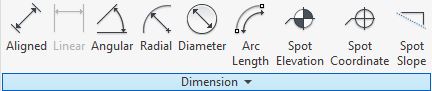
Alternatively you can access this units dialog box from the Annotation ribbon:
  • Click on the Dimensions drop-down arrow
  • Select the kind of dimension you want


Schedule Units Settings

  • In the Schedule Properties, go to the 'Formatting' tab
  • Select a field (on the left)
  • Click on the 'Field Format...' button on the right


  • Once you click on this, you get the standard Units dialog box
  • Typically the 'Use default settings' checkbox is ticked 
  • You can untick it if you want to over-ride the project settings


Tag Units Settings

Refer to Revit's Most Hidden Commands (part 2) for more detail on this.  It is quite tricky to find this setting:

  • Edit the tag family
  • Select and Edit a label

  • The parameter in the label may look like it is selected (on the left), but it is probably not
  • Select the relevant parameter (on left, even though it shows on the right)

  • The 'Properties' icon (a hand) will be enabled
  • Click on it

  • Finally you get to the units settings, which is normally defaulted to 'Use project settings'
  • It is not possible to get to this unit override setting within the project environment (unlike dimensions and schedules)

Summary

Here we have at least 4 completely different ways to access Revit units settings:

Method 1 (Ribbon in the project ):


Method 2 (Dimension Type properties in the project ):

or

Method 3 (Schedule formatting properties in the project ):


Method 4 (Tag properties in the Family Editor ):


Why does something so simple have to be so inconsistent, and complicated ?


Friday, 16 November 2018

Correcting the CL symbol in mirrored Revit links

The automatic 'Centreline' capability on Revit dimensions can be really annoying when they pop up unexpectedly.  But when you actually need them it is very useful to be able to just change a property of the dimension family to make the CL symbol appear.

I have seen people just placing many instances of two little pieces of overlapping text, one being C, the other L - all because they didn't know about this feature.  That is criminal!  And its a nightmare when dimensions need to be adjusted.

Mirrored Centreline Dimension Symbols

What happens when you mirror the elements and dimension?  In most situations, Revit handles it perfectly well, because the CL is a symbol family, and Revit automatically corrects the symbol orientation.  However, there is one situation where it does not work:
  • If the dimension is in a linked Revit file that has been mirrored - normally you would not see the annotation in the linked file, but if you set the view properties for that link to be 'By Linked View', then the dimensions in the mirrored linked file become visible.

  • In this situation, the symbol may not be displayed correctly, depending on how the symbol family was created:
CL symbol in Mirrored Link
  • The OOTB centreline family is actually made up of arcs and lines (not text) - this symbol does not display properly in mirrored linked files.
I was recently asked to solve this problem, so I searched high and low for settings in the dimension and in the symbol family that might solve this.  I found nothing.
  • Next I tried converting the symbol from lines to actual text in the family - I'm not sure why it was originally done as lines anyway?
  • This needs to be made up of two pieces of overlapping text - in the symbol family, not the project file.
  • In this example I made the text using a font that was clearly not lines - 'Algerian' was the first suitable windows font that I found, to make the demo clear.

  • In the original file it looks fine, as expected.
  • Once I looked at it as a mirrored linked file, another problem showed up:
  • Each letter was displayed correctly, but displaced sideways

  • Aha, it must be the text justification, I thought.
 
  • But no, that made no difference whatsoever when I tried centre, left or right Horizontal Align.  Revit is just mirroring each piece of text around the symbol centreline, then flipping the text back again around its own axis.

Weird Workaround

So what was the solution?
  • Edit the text in the symbol family - Put a space after the C and one before the L.
  • Shift the letters accordingly. 

  • It wasn't perfect to start with, so I had to shift the text around a bit, or add a second space after the L


Weird behaviour in Revit requires weird thinking workarounds!

Thursday, 2 November 2017

Weird Stuff with Revit Shared Parameters

When you create a suite of similar parametric families (say windows), you will define a series of parameters that control the families in the project - it may be dimensions, visibility switches etc.  If those are instance parameter, there is a really important choice you have to make:

  • Should they be "Shared Parameters" or just regular "Family Parameters"?

Conventional wisdom says that you only need to make them shared if you want to tag or schedule them in the project.  However, there are some other critical differences in behaviour that may affect your decision:

Did you know that when you make them 'Family Parameters', then start using the families in the project and swap them over for similar families with identical parameters - Revit loses the  data held in the instance parameters - even if the instance parameters are identically named in the families?  Aargh!!  That is not good news.  This even happens if the families were cloned from one source that already had the parameters set up.

However, if you used 'Shared Parameters' that instance property data is maintained when you swap family/types (provided that the same shared parameters are defined in each of the families).

Here is another reason for using shared parameters even when you don't need to tag or schedule them.

Monday, 19 June 2017

Global Parameter Enhancements in Revit 2018


I recently did a presentation on ‘Global Parameters’ at BILT ANZ 2017 in Adelaide.  I listed the two updates in Revit 2018 related to Global Parameters – one a bug fix, and the other being support for radius and diameter dimensions.  At the time I suggested that this was not a particularly interesting enhancement, and that I could not think of any particular uses for it.  However, in discussions with Frank Crisp of KTA (in Sydney), he came up with a brilliant idea for how to take advantage of this feature – so I have tested the idea and made a working example as follows.

Curved Curtain Walls

Everyone knows that Revit cannot do curved curtain walls – or at least the walls can be curved but the panels are flat, so that you get segmented curtain walls. 


In some situations this can be appropriate, but if you have enough budget for this, it may be desirable for the panels to curve too.  Some years back I created a curved curtain panel family but it was very clunky to use, and you had to manually match the radii of the wall and the panels.  Frank and I have now worked out a method to use global parameters to keep the radii in sync so that you don’t need to change the panel radius if the wall radius changes.  I have also improved my curtain panel family to make it much simpler to set up and to modify, as well as putting in some check formulas.

The Panel Family

My original curved curtain panel family had a series of reference line arcs in plan, running between the sides of the panel – one each for centreline, front and back of glass (and for any transoms).  These were used to define the outlines of vertical extrusions.  This was quite fiddly to set up and I have since learnt that it is much better to use sweeps for defining such geometry – this means that it is only necessary to draw one curved reference line to be used for the sweep path in plan.  All the sketch (or profile) geometry is drawn at the midpoint of the arc in a left or right view.  This means that an additional reference plane needs to be placed in plan at the furthest offset from the baseline or chord of the arc – this is used to host the profile sketches and it moves relative to the chord baseline depending on the radius of the arc and the length of the chord.
A formula is required to calculate this offset from the chord baseline – this dimension for the height of an arc above the chord is called a ‘Sagitta’.  Using Pythagoras’ Theorem it can be easily calculated from the chord length and the arc radius.  The radius is defined as the hypotenuse of the triangle (long side) while half the chord length forms one of the short sides (B).  The other short side (A) is calculated:
A = Square root of (C squared – B squared)
In Revit this formula is written as
A = SQRT(C ^ 2 – B ^ 2) 

The arc height (Sagitta) is simply the Radius (C) minus the short triangle side (A), so the overall formula is:
Sagitta = C - SQRT(C ^ 2 – B ^ 2)
where
B = Chord / 2
C = Radius


A few check formulas need to be put in as Revit does not like to calculate square roots of minus numbers, nor to have the radius equal or less than half the chord length.
The Radius parameter can be changed to ‘Radius desired’, which is the input value;  A new parameter ‘Radius actual’ checks the input value for anything less than or equal to half the chord length:
Radius actual = If(Radius desired > Chord/2, make it the Radius desired value, otherwise make it
the value ‘Chord/2 +1mm’).


In the Project

This curtain panel family can be loaded into a project and used in a curved curtain wall.  Initially the radius of the panels have to be manually set to match the radius of the wall.

If the wall radius is changed, the panel radii will be wrong


A curved wall does not automatically have a system property for Radius, so you need to add a dimension.


This dimension can then be associated to a global parameter but it must be a ‘reporting‘ parameter, so that all it is doing is getting the radius information from the wall element and pushing it back into the parameter for use elsewhere.


The curved curtain panel family can then have its radius matched to the curtain wall.  The ‘Radius desired’ property of each panel needs to be associated to the reporting parameter Radius of the wall.   

Alternatively, you can create a new global parameter that will represent the curtain wall radius if you need any calculations based on the reporting parameter.


Type vs instance

Depending on how you want to use the panels, the ‘Radius desired’ property could be either instance or type.  If you want to define the curved curtain panel as the default panel for this particular curtain wall type, then it must also be a type property.
If the curved curtain panel family Radius property is a type property, then you would need a panel type for each particular curtain wall otherwise it may break.  As a type property you only need to set it once regardless of how many panels you have in the curtain wall.

If the curved curtain panel family Radius property is an instance property, then you only need one panel type.  However, you need to associate the radius to the global parameter for each panel, which means extra work whenever the number of panels changes.


Warning: if you delete a radius dimension with an associated global parameter, it does not ask you if you want to remove the constraint.  This means you could end up with hidden constraints.