BILT Speaker

BILT Speaker
RevitCat - Revit Consultant
Showing posts with label symbol. Show all posts

Thursday, 4 June 2020

Which Kind of Callout to Use in Revit

Previously I have written about some of the limitations and inconsistencies with Revit Callouts:
There are some strange and frustrating restrictions, which mean you need to carefully plan how to manage Callouts.

Here I am going to describe the different ways to make Callouts in Revit, and propose a method of working that is different to the way Revit was designed, and probably different to how you use them.

Which Kind of Callout to Use?

1. Real Callout


The standard ‘Callout’ command places a rectangle defining the callout view extents. This will create a new view, and place the view reference rectangle on the active view. For reasons listed below, this method is not preferred.

  • You cannot change the reference.
  • You cannot move the callout to a different parent view.
  • You cannot change the callout view family between Plan/Detail (Plans only).
  • The callout rectangle can be stretched or rotated in the parent view – this will make the same change of extents or rotation to the callout view itself, which is not always desirable.
  • You cannot have the callout extents slightly different on the parent view (to make callouts readable) - they have to match the view cropping exactly.  Refer to Callout Crop-Boundary Mismatch.
  • If you copy and paste a Callout it creates an entirely new view with a different reference.
For more information see rules for Real Callouts

2. Reference Other View


Reference Other View Callouts can be created by:
  • Create a view to be referenced by the callout – eg. duplicate another view and crop it
  • Make sure the view is cropped (unless it is a drafting view).
  • On the view to place the callout, select the ‘Callout’ command, then select ‘Reference Other View’, and select a relevant view name from the drop-down menu
This method has many advantages:
  • Callouts can be moved to another view
  • Callout references can be changed to refer to different view
  • References will update if the view/sheet number is changed
  • Callouts can be copied to another parent view
It also has a few disadvantages:
  • It is possible for the user to select the wrong view in the list - there is no automatic check for this.
  • If you want to have "Sim" showing on a callout for similar details on multiple callouts, that is a Type property of the view being referred to, not a property of the callout symbol. 
    • That means it is all or nothing - ie. all instances of the callout must have "Sim" or not. 
    • It also changes the view type so it may move in your project browser, depending on your browser organistion.
  • You have to manually create each callout view (by Duplicate or Duplicate Dependent); then crop that view - this is a small price to pay for the benefits.
    • You could probably automate this using Dynamo.

3. Intersecting Views

Section callout symbols can be created automatically by Revit in section views – this occurs when one section has its extents completely within the larger section (both crop boundaries and clipping extents).
I would not recommend trying to use this method:
  • It is very confusing for users - it is better to stick with one Callout method for consistency.
  • Such callout sections may appear/disappear as view extents change

4. Fake Callouts 

Last and very much least, is a method that you should never, never use - but I've seen it often.
Fake (or dummy) view callout references can be made out of detail components or detail lines and text. This is very bad practice:
  • These may look like genuine Callouts, so people may not check the references. 
  • References will not update if view/sheets are changed.
  • This is totally against everything that Revit is trying to do!

Workflow Opinions

The following are my recommendations for working with Callouts in Revit.  Please note that these are opinions only - it is up to you to look at all the reasons I have given, and make up your own mind about this.  I accept no blame if it does not work for you.

One: All Callouts by 'Reference Other View'

Use method 2 (Reference Other View) for every single callout in your project.

If you never use methods 1 (Real Callouts), 3 (Intersecting Views), 4 (Fake Callouts), you will ensure consistency and will avoid most of the problems related to Callouts.

Two: Do Not Use Detail Views

Avoid using the Revit view family of 'Detail Views' - these have so many limitations and quirks, it is just not worth it.  Always use Plan views or Section views.  Refer to Detail Plan Callout Views

NB. If you follow the first recommendation above, this will not be an issue because it is only possible to create new detail views by Real Callouts.

Three: No Fakes

Never, never, never, never, never, never, never, never, never, never use method  4 (Fake/dummy Callouts).  It is much quicker and safer to use 'Reference Other View' callouts.
Anyone who does this in Revit should not be using Revit at all !

Reference Label

There is one problem with using only 'Reference Other View' - refer to 'Reference Label'

Feedback

I would be very interested to hear whether anyone has different (or the same) opinions about using Callouts - feel free to comment.

Friday, 16 November 2018

Correcting the CL symbol in mirrored Revit links

The automatic 'Centreline' capability on Revit dimensions can be really annoying when they pop up unexpectedly.  But when you actually need them it is very useful to be able to just change a property of the dimension family to make the CL symbol appear.

I have seen people just placing many instances of two little pieces of overlapping text, one being C, the other L - all because they didn't know about this feature.  That is criminal!  And its a nightmare when dimensions need to be adjusted.

Mirrored Centreline Dimension Symbols

What happens when you mirror the elements and dimension?  In most situations, Revit handles it perfectly well, because the CL is a symbol family, and Revit automatically corrects the symbol orientation.  However, there is one situation where it does not work:
  • If the dimension is in a linked Revit file that has been mirrored - normally you would not see the annotation in the linked file, but if you set the view properties for that link to be 'By Linked View', then the dimensions in the mirrored linked file become visible.

  • In this situation, the symbol may not be displayed correctly, depending on how the symbol family was created:
CL symbol in Mirrored Link
  • The OOTB centreline family is actually made up of arcs and lines (not text) - this symbol does not display properly in mirrored linked files.
I was recently asked to solve this problem, so I searched high and low for settings in the dimension and in the symbol family that might solve this.  I found nothing.
  • Next I tried converting the symbol from lines to actual text in the family - I'm not sure why it was originally done as lines anyway?
  • This needs to be made up of two pieces of overlapping text - in the symbol family, not the project file.
  • In this example I made the text using a font that was clearly not lines - 'Algerian' was the first suitable windows font that I found, to make the demo clear.

  • In the original file it looks fine, as expected.
  • Once I looked at it as a mirrored linked file, another problem showed up:
  • Each letter was displayed correctly, but displaced sideways

  • Aha, it must be the text justification, I thought.
 
  • But no, that made no difference whatsoever when I tried centre, left or right Horizontal Align.  Revit is just mirroring each piece of text around the symbol centreline, then flipping the text back again around its own axis.

Weird Workaround

So what was the solution?
  • Edit the text in the symbol family - Put a space after the C and one before the L.
  • Shift the letters accordingly. 

  • It wasn't perfect to start with, so I had to shift the text around a bit, or add a second space after the L


Weird behaviour in Revit requires weird thinking workarounds!

Sunday, 11 March 2018

The Revit Pin Icon

So you think you know what the pin icon in Revit looks like, and exactly what it means?  Think again - the icon actually changes all the time, depending on the situation and sequence of events.


Most elements can be 'Pinned' in Revit to make them more stable:  when an element is pinned in Revit, it cannot be moved, deleted or edited without unpinning it – but there are exceptions . . .

The Ribbon Pin Icons

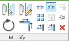
When you select an element in Revit, the ribbon displays a 'Modify' panel with two icons for pinning/unpinning (top right of the panel):

These icons are used as command functions to operate on the selected element(s); they also indicate what command is possible on those elements - in effect, showing the current 'pin state' of the  element, but in a confusing way:  the greyed out icon indicates the current state.
  • The lower right 'Pin' icon will be available if the element is not pinned
  • If the element is already pinned, it will be greyed out
 
  • The upper right 'Unpin' icon will be available if the element is already pinned
 
  • If the element is not already pinned, it will be greyed out
  • If multiple elements are selected, and some are pinned, some not, then both pin and unpin icons become available, so you can no longer tell the state of any of them from the ribbon icons.
 

Element Selection Pin Icons

The icons that display on the selected element operate in the more logical (but reverse) fashion - as well as being command functions when clicked on, they do actually indicate the current 'pin state' of the  element(s).
  • Each element has its own icon, so you can tell the state of each one.
  • Pinned elements show a blue 3D pin icon
  • Elements that were once pinned but are now unpinned sometimes show a blue pin with red cross - but it depends on how it was unpinned.
This is where it starts getting tricky:
  • If you click on the blue pin icon on the element, Revit now will show a red line through the pin to indicate it is now unpinned but was previously pinned - this can be a good reminder that you should repin it after performing some edit operation on it.
  • Revit remembers this 'previous pin state' even when you close the session and open the model again later - when you select the element it still shows the blue unpinned icon - I like to refer to this as temporary unpinning.
  • However, if you use the ribbon command icon to unpin, then the blue element pin icon totally disappears - I like to refer to this as permanently unpinning.
The keyboard shortcut to permanently unpin elements is ‘UP’. Multiple elements can be unpinned at one time using the UP shortcut.  There is no keyboard shortcut for the temporary unpin command.

This difference between the two operations is almost like a partly implemented idea for a proper temporary unpin command - I wish that Autodesk would take it one step further and give us a proper temporary unpin (or persistent pin):  this would allow us to unpin an element, then edit it, after which it would automatically repin itself.  There is a precedent for this in Revit with the temporary 'Exclude Options' selection checkbox (which rechecks itself automatically).
Feel free to vote for my Revit wishlist idea for Persistent Pins


Selection Settings

In the bottom right corner of the Revit window are the orange selection pin icons, although these perform a totally different function:
  • They display the status of whether you will be able to select pinned objects or not - they also operate as switches between the two modes.
  • The red cross on the icon means that you cannot select any pinned elements.

Refer to Hidden Commands - Selection Locks

Pin Visibility

Element pin icons are not always visible:
  • In a workshared model, when you select an element, it displays the 'Workshare puzzle' icon - this will obscure any pin icons
  • To see the pin icons you have to take ownership of the element(s)
  • you can click directly on the icon to remove it (and take ownership of the element), or right-click ‘Make Element Editable’ to take ownership and remove the puzzle icon.


Pin icons may also be hidden by group add/remove icons if you select an element inside a group without editing the group.


The way around this is to edit the group

Chain-Pins


Chain-Pinned ‘hosted elements’ (eg. Curtain panels) behave completely differently to normal pinned elements.  However, the icon for this is very similar - it has a chain link next to the pin.
The same pin/unpin commands and ribbon icons are used but they operate in a quite different way

Refer to Chained / Pinned Hosted Elements