BILT Speaker

BILT Speaker
RevitCat - Revit Consultant
Showing posts with label pin. Show all posts

Sunday, 20 May 2018

Revit Ideas Wishlist Voting

Autodesk created the 'Revit Ideas Wishlist' a while back - yes I know it is flawed and has a lot of rubbish on it.  However, I know that the Revit Product Managers do actually look at it and monitor the votes.  It is not the only thing that decides what goes into future Revit upgrades but it contributes to the discussion - so I like to support it, in particular the sensible ideas that are posted on it.

I do believe that we should mainly be voting for things to be done to the core software that cannot be done by API, Dynamo or Add-ins - as those things can be done quickly by others (or yourselves).

Here are some of the better ones that I think should be voted up (including some that I have posted):

Please go to the Revit Ideas forum and vote for any of these ideas that you agree with:

Model Stability (& Pins)


Allow us to change 2D extents of pinned sections - just like we can for grids and levels.  Then we could leave those sections pinned all the time and not risk losing attached annotation.

Persistent Pins - pins that reinstate themselves after you have modified the element once

Parameters


#1 wish regarding parameters is to allow Shared Parameters in Key Schedules  - this would unlock so much potential in Revit, and the API just can't get in there to solve it.

There are several outstanding Global parameter requirements:

The first is oh so simple, but would be a huge deal for us:
Enable global parameters to associate to Floor ‘Height Offset from Level’ system property

Enable global parameters to associate to Array Numbers

Enable creation of an Area Reporting Parameter for use in Global Parameters

For more detail  refer to Global Parameter wishes


Stairs & Railings


There are so many things that need to be fixed on stairs and railings, that I have created a list of requests just for Stairs and Railings.

There are a couple of basic ones that just need to be done to improve stair arrows - not much more than bug fixes:


Families

Are you intensely irritated by the default setting for face-based family placement being 'Place on Vertical Face'?  I think that 99+% of users would like it to be changed (not to mention BIM managers who have to deal with confused users not understanding why they can't place ceiling fittings).
Vote her to  make the default 'Place on Face'


Form Creation

Creating forms in the Conceptual Massing Environment is fraught with problems - some of them could be alleviated by the following two capabilities:

Control profile order during form creation

Select Path during form creation

There are oh so many more things that need to be fixed in Revit - but since Autodesk concentrate on such a few, we need to target which ones would genuinely benefit the most people.  And we shouldn't ask Autodesk to spend time on things that can be done by some other means (API, Dynamo etc).

Have a look at the latest updates to the Autodesk Revit development roadmap to see what is planned or has been recently delivered.

Saturday, 28 April 2018

New in Revit 2019 - Levels in 3D Views

One of the new features in Revit 2019 is the ability to see Levels in 3D views.

Personally I don't like this enhancement!  Yes, I know that occasionally someone might have valid reasons to see a level in 3D, but I don't think it is worth the pain it will inevitably cause around the world over the next few years!
I can foresee levels being accidentally moved, copied and having their model extents inadvertently changed on a regular basis.

Reasons why I don't like it:

Cropping View Extents vs Model Extents

  • The grip handles for levels in a 3D view are typically model grip handles (a circle), not view grip handles (a dot).  It is not possible to adjust just the 2D view extents when levels are  uncropped in the view - so any changes you make to the levels will affect the model extents and therefore many other views. 
  • When I say 'uncropped levels' in a 3D view, I don't mean uncropped by the 'View Crop Region' because that has no particular relevance to levels in 3D - they just get partially hidden like all other elements at the crop boundary.  This is quite different behaviour to a section or elevation view where they would independently extend beyond the view crop boundary.  This behaviour in 3D is not unexpected or unwelcome as rotating a 3D view could cause havoc if they did extend past view crop regions.

There are ways to crop levels in 3D views, and to adjust view extents, but its a whole lot more complex than doing so in a section/elevation view:

Section Box

  • If you apply a section box to a 3D view then it will also crop levels, in a similar way as it does in a section/elevation view.  But not the same!
  • The levels will automatically be cropped to the section box, plus a default extension past the crop - much the same as a 2D view.  
  • But that means their view extents can be made smaller or bigger, depending on the size of the section box - if the section box is bigger than the original level model extents, they will be bigger in the view (sometimes dramatically bigger).  Yikes, that doesn't happen in section views!
  • There is an exception to this rule, and that is when the levels are controlled by a Scope Box - see next method.

Scope Box

  • When a level has a 'Scope Box' applied to it then all the above rules go out the window, and the Scope Box takes precedence, and it completely ignores a section box.
 
  • This can be good if you want the levels to be cropped to something small while the section box is large
  • Or it can be bad if you have a very small section box


This can be interesting to manage if you have two sets of levels in one model (eg. for different towers):
  • Starting without any cropping or scope boxes it looks OK in 3D
     
Two sets of split-levels; no section box, no scope boxes
  • Add a section box and all hell breaks loose:
Add Section box - view extents overlap for all levels

  •  Once you apply Scope Box properties to the levels it gets it back under control
Add Scope Box control to levels

  •  Until you make the section box really small - yuk!
Not so good with a small section box
  • I guess you'd have to then use a crop region on the view and start hiding the levels you don't want to see, to solve that one.

2D vs 3D Grip Handles

When a level is uncropped by either method described above, the grip-handles on a level in 3D only show model extents (circle grip)

  • Once the level is cropped (either by a scope box or a section box), the grip-handles become view specific (blue dot) - this is the only way I can see to get this to happen in 3D views.


  • Unlike a section or elevation view, you cannot toggle the grip handles between 2D and 3D (whether the levels are cropped or not)
  • When the grip-handles are view related, they do give you the option of aligning and locking the ends of multiple levels, so that you can adjust several at once - that is a good thing.


  • You cannot lock a series of aligned levels and drag their model extents all at once in a 3D view - Unlike a section or elevation view,where you can lock them. 
  • Yes, I know that most of the time you would not want people to be able to change the model extents of a level in 3D at all, let alone multiple levels;  however, a 'Model manager' may want to fix up levels in 3D since it is sometimes really tricky in section when they don't show up.  

  • Unlike a section or elevation view, when you drag the grip handles in 3D, the level extents do not snap to line up with other levels.  That is really irritating.
  • It will be a waste of time trying to align model extents of multiple levels in a 3D view by dragging the grip-handles (reasons above), as they will never perfectly align with each other.  OK, so use Scope Boxes instead!
  •  When a level is pinned (and cropped in a 3D view), you can still adjust its view extents without unpinning it - thank goodness.
 
  • Levels can be accidentally selected in a 3D view and then deleted, moved, copied etc  - previously this could only be done in a section or elevation view, where levels were much more obvious (hence less likely to be accidentally selected).  Now there are many more chances for people to mess up your model!


During beta testing I lobbied really hard to stop this feature being released in its current form (if at all), because of the reasons above.  I lost that battle, but a few good things did come out of the discussion - they gave us a new safety check feature:
  • We now have a new warning dialog box when you delete a level - it warns you that associated views and elements will be deleted.  This is a very welcome side-effect of the 3D Levels.


View Visibility

  • When you upgrade an old project to 2019, Levels will not be visible by default in existing 3D views - you would need to go to Visibility Graphics to specifically turn them on.
  • However, in new projects they will be visible by default in 3D views. Apparently Autodesk were keen for this new 'enhancement' should be more discoverable!
  • It appears that for new 3D views in upgraded projects, they will also be visible by default.   Aaargh.
  • Thankfully that does not apply to perspective views, where
    Incidentally there is a way to set up your projects so that new 3D views will have levels hidden, using a default 3D template - more on that in another blog post.

Conclusion

Over the last few years Autodesk have been slowly but surely giving us more ways to lock down our models and make them more secure.  And now they have opened another can of worms - largely as a response to significant user demand (on the Revit Ideas Wishlist, amongst other places).  

Ah well, that's the danger of listening to popular votes (open wishlists) instead of the experts!

So where does that leave us?  There are several things you can do to minimise the risk:
  1. Don't upgrade to 2019 until Autodesk fixes the issues described above (2019.1?   .2?   2020?) - but you'd miss out on the other goodies such as view control / multiple monitor support etc!
  2. Make sure that all levels are pinned all the time.  ALL THE TIME.   Make sure that your users understand the selection locks so they can prevent selection of pinned elements.
  3. Use Scope Boxes to manage the model extents of your levels. This would be good practise anyway in most cases, as it gives you better control and locks them down somewhat.
     
  4. Teach your users how to manage these issues and make sure they really understand the difference between view and model extents of levels (and grids, and sections), and between scope boxes vs section boxes.
     
  5. Set up a default 3D view template that has levels (and scope boxes) hidden, and set it to apply to all new 3D views.

Monday, 9 April 2018

To Pin or Unpin? that is the Revit Question

Following on from several recent posts about 'Pinning' elements in Revit, there are a few more subtleties to mention.  There are also some exceptions to the general rule of not being able to edit pinned elements.


Refer to these other posts on Revit Pins:

Modifying Pinned Elements

A pinned element cannot be moved or rotated, but it can be copied
  • If you try to move a selection that has any user-pinned elements, Revit will attempt to move them all (graphically showing the move) then warn you that they cannot be moved – so it puts them back and nothing happens.  This is a time-waster, so it is better to check for pin icons before moving large selections - and use the selection filter to check for hosted subcategories. 
  • NB. It is not sensible to just click on the unpin icon on the ribbon before moving the selection - if you had any curtain walls or handrails, it would also unpin all the chain-pinned (type-driven hosted) curtain grids, panels, mullions and handrail supports - thus destroying the integrity of the model.
A pinned element cannot normally be deleted;
  • If you try to delete a selection that has any pinned elements, Revit will behave quite differently to trying to move them:  If some elements in your selection are pinned, and some not, it will delete the unpinned elements and warn you about not deleting the pinned ones
  • Revit will warn you about what is happening, but it is sensible to stop and think about what it has just done - and your next steps:  The undeleted elements are no longer selected, so it may be tricky to reselect the same ones?

Modifying Unpinned Elements

Once an element has been unpinned, you might think that it could be freely edited - but of course that is not true of 'Chain-Pinned' or type-driven hosted elements such as curtain panels, grids & panels.  there are some tricky rules and exceptions here:


Deleting Chain-Pinned Elements

  • Unpinned type-driven Curtain Wall Mullions can be deleted;
  • Unpinned type-driven Curtain Wall Grids cannot be deleted (but segments can be 'removed', laboriously, one by one);
  • Unpinned type-driven Curtain Panels cannot be deleted - but you can change them to an 'Empty System Panel' (if you haven't purged the last type from your project, that is;  if you have purged it, you can't just create a new type of empty system panel, you have to copy one from elsewhere);
  • Unpinned Railing Handrail supports can be deleted

Moving Chain-Pinned Elements

Chain-Pinned elements can only be moved within the constraints of their relationship to the parent element.  For example:
  • Unpinned type-driven Curtain Wall Grids can be moved in one direction only;
  • Unpinned type-driven Curtain Wall Mullions and Panels cannot be moved except by changing their properties, such as Offset;
  • Unpinned Railing Handrail supports can be moved along the handrail - but there are some extreme weird behaviours when you try to do this.

Editing Chain-Pinned Elements

 The only Chain-Pinned elements that can be edited after unpinning are curtain panels – using the ‘Edit In-Place’ functionality.  In fact this allows you to do some crazy stuff with panels, which is quite surprising given all the other restrictions that prevent you from creating buildable elements!


Editing Pinned Elements

You would think that you cannot edit any pinned elements, but you would be wrong!

Floors (and other sketch based elements)

Pinned floors cannot be directly edited – the Edit icon is greyed out


Pinned floors can be modified (without editing the boundary) – by moving associated walls, depending on how the floor edges were defined:
  • If the floor edge is defined by ‘Pick Wall’, the floor edge will move with the wall, even when the floor is pinned

  • If the floor edge was done using ‘Pick Line’ or just drawing a line on/near the wall, when the wall is moved, the floor edge may still move with the wall, even if the sketch line was not locked to the wall.  The rules are not clear on this.

  • This happens even if the floor sketch lines themselves are pinned when editing the floor. 
  •  If a floor is moved, any pinned sketch boundary lines will just move with the whole floor - rendering the pin command inside a sketch pretty useless.
  • Other pinned sketch-based components such as roofs, ceilings etc behave like floors.
This means that Wall Associations are stronger than pins in Revit.

Moves With Nearby Walls

An element that has been pinned, and has its property 'Moves With Nearby Elements' ticked will completely ignore the pin and move when a nearby wall moves

Wall associations win again!

Groups

Pinned Groups can be edited (without unpinning) - this is not the same behaviour as floor sketches.  However, it is not a bad thing in itself, as it means you can pin all groups all the time.
  • Pinned elements inside a group will be moved or deleted when the parent group is moved or deleted, without so much as a 'By your leave'.

Properties

Instance & Type properties of pinned elements are generally editable - this means that such things as Base level or offset could be changed, thus rendering the 'Pin' less effective than you thought.


Modifying Pinned Datums

When a datum element (grid, level or reference plane) is pinned, you cannot change its 3D extents - not surprisingly.
  • However, you can change its 2D extents in each view - which is a jolly good thing, because you can pin them, and leave them pinned!

Section Line

When a section line is pinned, you cannot change either its 3D or 2D extents.  In fact it does not display the extents or depth of view in plan when you select it.  This is an immensely frustrating and dangerous inconsistency in Revit.  It really ought to behave just like datums so that you could change its 2D extents, and at least see its depth of view - it is ironic that you can change the depth of view of a pinned section using the properties dialog box.

As soon as you unpin the section, you can adjust 2D, 3D extents and depth of view graphically in plan.  The big danger here is that you might forget to repin the section line, and some other fool may then move or delete your section line (along with all its carefully lined up 2D annotation).

For this reason it is wise to use the pin icon on the section line itself to unpin it - that way it retains the unpinned icon as a reminder to repin it immediately afterwards [If you use the ribbon unpin icon, it does not retain the unpinned icon on the section line itself]

Please go to the Revit Ideas forum and vote for 'Allow us to change 2D extents of pinned sections'

I am sure there are plenty of other examples of pinned elements in Revit that can be edited when you do not expect to be able to do so (or vice versa).

Sunday, 11 March 2018

The Revit Pin Icon

So you think you know what the pin icon in Revit looks like, and exactly what it means?  Think again - the icon actually changes all the time, depending on the situation and sequence of events.


Most elements can be 'Pinned' in Revit to make them more stable:  when an element is pinned in Revit, it cannot be moved, deleted or edited without unpinning it – but there are exceptions . . .

The Ribbon Pin Icons

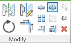
When you select an element in Revit, the ribbon displays a 'Modify' panel with two icons for pinning/unpinning (top right of the panel):

These icons are used as command functions to operate on the selected element(s); they also indicate what command is possible on those elements - in effect, showing the current 'pin state' of the  element, but in a confusing way:  the greyed out icon indicates the current state.
  • The lower right 'Pin' icon will be available if the element is not pinned
  • If the element is already pinned, it will be greyed out
 
  • The upper right 'Unpin' icon will be available if the element is already pinned
 
  • If the element is not already pinned, it will be greyed out
  • If multiple elements are selected, and some are pinned, some not, then both pin and unpin icons become available, so you can no longer tell the state of any of them from the ribbon icons.
 

Element Selection Pin Icons

The icons that display on the selected element operate in the more logical (but reverse) fashion - as well as being command functions when clicked on, they do actually indicate the current 'pin state' of the  element(s).
  • Each element has its own icon, so you can tell the state of each one.
  • Pinned elements show a blue 3D pin icon
  • Elements that were once pinned but are now unpinned sometimes show a blue pin with red cross - but it depends on how it was unpinned.
This is where it starts getting tricky:
  • If you click on the blue pin icon on the element, Revit now will show a red line through the pin to indicate it is now unpinned but was previously pinned - this can be a good reminder that you should repin it after performing some edit operation on it.
  • Revit remembers this 'previous pin state' even when you close the session and open the model again later - when you select the element it still shows the blue unpinned icon - I like to refer to this as temporary unpinning.
  • However, if you use the ribbon command icon to unpin, then the blue element pin icon totally disappears - I like to refer to this as permanently unpinning.
The keyboard shortcut to permanently unpin elements is ‘UP’. Multiple elements can be unpinned at one time using the UP shortcut.  There is no keyboard shortcut for the temporary unpin command.

This difference between the two operations is almost like a partly implemented idea for a proper temporary unpin command - I wish that Autodesk would take it one step further and give us a proper temporary unpin (or persistent pin):  this would allow us to unpin an element, then edit it, after which it would automatically repin itself.  There is a precedent for this in Revit with the temporary 'Exclude Options' selection checkbox (which rechecks itself automatically).
Feel free to vote for my Revit wishlist idea for Persistent Pins


Selection Settings

In the bottom right corner of the Revit window are the orange selection pin icons, although these perform a totally different function:
  • They display the status of whether you will be able to select pinned objects or not - they also operate as switches between the two modes.
  • The red cross on the icon means that you cannot select any pinned elements.

Refer to Hidden Commands - Selection Locks

Pin Visibility

Element pin icons are not always visible:
  • In a workshared model, when you select an element, it displays the 'Workshare puzzle' icon - this will obscure any pin icons
  • To see the pin icons you have to take ownership of the element(s)
  • you can click directly on the icon to remove it (and take ownership of the element), or right-click ‘Make Element Editable’ to take ownership and remove the puzzle icon.


Pin icons may also be hidden by group add/remove icons if you select an element inside a group without editing the group.


The way around this is to edit the group

Chain-Pins


Chain-Pinned ‘hosted elements’ (eg. Curtain panels) behave completely differently to normal pinned elements.  However, the icon for this is very similar - it has a chain link next to the pin.
The same pin/unpin commands and ribbon icons are used but they operate in a quite different way

Refer to Chained / Pinned Hosted Elements