BILT Speaker

BILT Speaker
RevitCat - Revit Consultant
Showing posts with label support. Show all posts

Saturday, 26 January 2019

How Do You Solve a Problem Like Ma Railings?


Have you ever encountered a problem with out-of-control railings in Revit?  OK, so maybe the structure shown above is not a haywire railing, and was meant to be like that, but most Revit users have struggled with trying to model railings as they should be.

How Do You Solve a Problem Like Ma Railings (in Revit)?  *


* with apologies to Richard Rodgers for misappropriating his song title (How Do You Solve a Problem Like Maria? from the Sound of Music, By Rodgers and Hammerstein) - not to be confused with Richard Rogers (no d), the architect who designed many famous buildings, such as the Pompidou Centre in Paris (with Renzo Piano) and the Lloyds Building in London.

Richard Rogers surely did not struggle with trying to model railings in Revit, as those buildings were designed long before the advent of such software.  These days we certainly do struggle with the software - Revit has been around for almost 20 years and it still it does not enable us to model Railings the way we want them (except for the most simple handrail).  There are many problems with the railing tool in Revit, some of which have been documented on this blog - see the list below.  Over the years, we have benefitted from several minor improvements to the railing tool - for which we are very grateful.  However, there is one fundamental problem that has not been resolved - and that is the inability to control the location of individual balusters.

Baluster Placement - a Fundamental Flaw

The railing sample file shows some relatively complex looking examples - but these are just straight runs on the level.  As soon as you try to use them on stairs, things start going wrong with the baluster placement.

This example is done using two alternating balusters - one is just a post, while the other is glass with fixings.  The glass baluster is very good at adjusting the angle of its top and base (if you create the family properly). 
 
When it comes to spacing, it is pretty hopeless:  you get gaps whenever there is a break in the pattern.
Standard railing with glass balusters
There are some limited controls within the baluster placement type properties, but no single combination of settings will ever work on the whole stair railing.

Spreading the pattern to fit does resolve some issues, sometimes. . . .

Changing the 'Break-Pattern' property to 'Never' can have some weird results

Reverting the pattern to 'Centred' does not fix it either - you may end up with panels across a change in angle, where the panel is not trimmed properly.

Workarounds

There are a number of ways that people get around these problems, but none of them is satisfactory:

1.  You can try using 'Handrail Supports' to represent balusters, but that has at least two problems:
  • Handrail supports do not respond to changes in angle of the stair, so you need to build that in as a user control that has to be manually set every time
  • Handrail supports can be unpinned and then moved (or changed to another type), but the moving process is very tricky - see Moving Handrail Supports
    It is also possible to very easily lose the positions by accidentally resetting the railing.
2.  Model the glass as a continuous rail element, use balusters and/or handrail supports to represent the fixings and vertical joints in the glass.  More on that another time.

3.  Model the railing 'in-place'.  This is a really bad idea as it screws up the subcategories, visibility etc;  And worse still, it does not update when the stair changes

4.  Just model a Top Rail / Handrail (with no balusters), which shows up in plan.  Document the railing in 2D as drafting views or as detail elements on stair sections.  This is a terrible solution (very un-Revit-like), but it can save huge amounts of modelling time - so it is done quite commonly in the industry.  Of course, it can lead to errors on site . . . .

Railing Fixes

If we had the ability to control the baluster placement in much the same way that curtain walls operate, it would help resolve this fundamental flaw in the railing tool;  this would require the ability to include variable width panels too.  Of course there need to be many other minor fixes in addition to that. 

On the Autodesk Revit Roadmap, Railings were flagged as 'fixed', a couple of years ago, on the basis of a number of minor enhancements.  Clearly it is nowhere near being fixed - see this request on 'Revit Ideas'  Railing Overhaul - Resolution of Limitations - from Chris Price (Mr Spot).

Weird Railing Stuff Blogs

Over the last few years I have posted many blog articles on the many weird quirks of using Revit to model Railings.  Some articles just document the inconsistencies and strange behaviour - just so you know what is going on; other articles offer some workarounds and ground-rules that might help you along:

Revit Railing Enhancement Requests

Autodesk  have a 'Revit Ideas' website that allows you to vote for enhancement requests.  I have compiled a list of stair/railing related ideas - please, all of you vote for some of these requests - if you don't vote, Autodesk will continue to consider them as fixed.

Sunday, 13 January 2019

Weird Railing Stuff - part 16 - Rail Hand Clearance Property

Following on from my previous post about Railing Offsets, here is some more detail about the ludicrously inconsistent UI for Handrails and Top Rail offsets in the 'New-style' railings.

Handrail Offsets

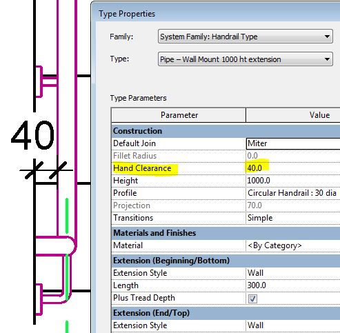
Handrails can only be moved laterally within the Handrail Type Properties (not in the railing properties).  This is controlled by a property called 'Hand Clearance'


The Hand Clearance property dictates how far the inside face of the Handrail is offset from the 'Notional Railing Centreline', which is not necessarily where the wall or other railing elements are*.

  • The Handrail family has a ‘Hand Clearance’ property, and projection property (see below)
  • In trying to use a real-world term, Autodesk have muddied the waters and made it totally confusing to work with.  This property is only logical with certain types of railings:
    • one example might be a wall-mounted handrail that has no other linear elements; and even then it only works when the Railing 'Offset from Path' property is set to zero.
    • If the railing has balusters and posts, with a Handrail mounted on those, the ‘Hand Clearance’ property does not take account of the baluster/post width, so you'd need to add in half that width yourself.

Once the Hand Clearance property is set in the Handrail family, you have to go back to the Railing family to see the effect it has on the whole railing, where the calculated Lateral Offset is displayed (not shown in the Handrail properties).

The Lateral Offsets are calculated by the system, depending on the Handrail type properties.  Typically this should be:
  • Hand Clearance + (Profile Width / 2)    - in this case  40 + 30/2 = 55mm.  
  • The Lateral Offset represents the centreline of the Handrail relative to the notional centreline of the whole railing (which is itself moved around by the 'Offset from Path' property).
  • If you want a centred Handrail, you need to make its hand clearance property minus half the profile width
Projection Property
  • There is another calculated property that is displayed here: 
    'Projection', which is calculated as (Hand Clearance + Profile Width)
    It is again greyed out, and updates immediately after any changes to the profile width or Hand Clearance.
  • I cannot see the logic of having this property displayed here, while the Lateral Offset is not.

Changing Properties

The knock on effects of any changes you make is again, a little confusing:
  • If you change the profile type, and hence its width then the 'Hand Clearance' is likely to change.  What Revit is trying to do is maintain the 'Lateral Offset' value, and hence the centreline location of the Handrail.
  • This may be logical to the software programmers, but not to designers, who would want to maintain the Hand Clearance when the profile width changes.  
  • The end result is that you need to pay careful attention, and manually change the Hand Clearance yourself after every profile change.
Once you have made any changes to the Handrail Type properties, then click OK, it returns to the Railing Type properties (if that is where you started from).  There is a display bug here:
  • The Lateral Offset does not appear to be recalculated (although it is).
  • To cause a display refresh, you need to change the value of the 'Position' to something else, and then back again.
  • Alternatively you could close the Type properties and reopen.

Wall-Mounted Handrails

In the case of Wall-Mounted Handrails, where there are no Top Rails or Balusters, the settings need to be somewhat different - and this is about the only situation where the term 'Hand Clearance' makes any sense.

The Railing Instance property 'Offset from Path' needs to be set to zero.  It is very frustrating that this is not a Type property, or at least have a default value stored within the Type properties - as you need to remember to set it to zero every single time you place a railing of this type.

The Handrail Type properties should be set with the actual Hand Clearance that you want - say 40 or 50mm.

Make sure that you choose the correct profile size first, as Revit will alter the Hand Clearance if you change the profile.

The Railing Lateral Offset property will be set automatically.


Top Rail Offsets

  • The Top Rail family also has a ‘Hand Clearance’ property, and projection property.
  • This is confusing - the Top Rail is meant to be there to support other railing elements, although it may double as a handrail. Whether it serves as a handrail or not, it would typically be centred with balusters etc on the 'Notional Railing Centreline', which is what the Hand Clearance value is measured from. 
  • Just to make it doubly confusing, the Top Rail offset is inconsistent with Handrail offsets:  a positive Hand Clearance value moves the Top Rail outside the stair in plan (Handrail moves inside stair).
  • Although the calculation for Lateral Offset is the same, it moves the opposite way:
    • (Hand Clearance + Profile Width / 2) - in this case  -25 + 50/2 = 0mm
  • If you want a centred Top Rail, you need to make its Hand Clearance property minus half the profile width of the Top Rail.

If you set the Hand Clearance to zero, you would get a Top Rail offset by half its width from all the balusters (unless they also had offsets . . .)


Here is  more information on the inconsistency between Top Rail and Handrail Terminology

Thursday, 6 December 2018

Weird Railing Stuff - part 13 - Handrail Support Family Types

Is this a Railing Bug?  Or is it the UI 'As Designed'?
Either way, it is yet another example of how the railing interface in Revit needs some serious attention.

Support Family or Type?

 As you all know, it is entirely possible to have numerous different families that all have the same Type names, in a Revit project.  This can happen for a number of reasons, including the mysterious bug whereby families get renamed with a number suffix when copying elements into a project that already contains that family.  These families may or may not be the same


When selecting a support family type in a handrail family, it only lists the Type name – so that if two different families have same type name, you can’t tell the difference


 In addition, the list of family/types does not appear to be alphabetical - so the order may easily be different to the order in the Project Browser.

Note that in the Handrail Type dialog box, the parameter is labelled as 'Family' when in fact it is listing Types only.  In the Railings dialog box, the parameter is labelled as 'Type' - yet another inconsistency!

Friday, 20 April 2018

Dynamo and Revit 2016 vs 2019

When I installed Revit 2019 recently, I uncovered a problem that will undoubtedly affect some other people - in fact there is already some buzz about this issue on the forums:


Dynamo Versions

The latest versions of Dynamo do not support Revit 2016. 
Refer to DynamoBIM blog


The theory behind this is that the Autodesk Dynamo team are working to a system whereby only three consecutive annual releases need to be supported by any version (2016, 2017, 2018  or 2017, 2018, 2019).  Typically Autodesk Revit licenses are set up that way, to only allow 3 years - but its only a license issue, not an inbuilt Revit limitation.  However, Autodesk realise that in the real world it is very difficult to manage a Revit installation in a company where you have multiple projects that need to be on different Revit versions to match up with varied consultants on each project.  Supporting 4 versions of Revit simultaneously is quite common in the industry - and Autodesk will supply licenses for this accordingly if you ask them (or your reseller).

There are two new Dynamo versions available:
  • Dynamo 1.3.3   which is virtually the same as 1.3.2, except in the versions it supports
    Dynamo 1.3.2 supports Revit 2016, 2017 & 2018 (but not 2019)
    Dynamo 1.3.3 supports Revit 2017, 2018 & 2019
  • Dynamo 2.0 is a whole new 'Major Release' - it is not backward-compatible with previous versions (dyn and dyf files are saved in a new format)
    Dynamo 2.0 supports Revit 2017, 2018 & 2019
That means there is no one version that supports both 2016 and 2019 - not even a brief overlap in time while you are updating graphs, custom nodes & packages.

Dynamo 2.0 graphs and custom nodes cannot be opened in 1.xx versions.  Some or most Dynamo 1.xx graphs and nodes will work in Dynamo 2.0 but there is no guarantee - see DynamoBIM Blog 2.0 and Beyond for more detail. 

It is possible to have two parallel installations of Dynamo 1.3.2 (or earlier) and 2.0 - both of which would run on Revit 2017 & 2018 (you get a choice of which to run when you start Dynamo) - but only one of those two versions would run on either Revit 2016 or 2019 (unless you have 1.3.3 and 2.0 which could both run on 2019).

I don't think that you can have both 1.3.2 and 1.3.3 running in parallel like this - I have not tried it, but that is the word I see on forums.  I believe that one install messes up the other - and you can't choose which versions of Revit to install Dynamo to.

 If you do want to have two versions of Dynamo installed (one being 2.0), you will need to maintain two versions of all your graphs, custom nodes and packages.  And don't get them mixed up!

If you have any projects still in v2016, you will need to consider very carefully how you handle your Dynamo versions.  I would personally recommend that you hold off Dynamo 2.0 until you are quite certain you won't ever need to do anything in Dynamo in Revit 2016 - once you make that leap to 2.0 there is no going back.

It would be really helpful for us if Autodesk were to give us a version of Dynamo (1.xx) that is just like 1.3.3 but supports Revit 2016 too (ie. 4 consecutive Revit versions).  I believe there is no technical reason why not - its just a decision making process at Autodesk.  That would help us get over this tricky version management situation until things have moved on a bit - then we can all stop using Revit 2016 and the Dynamo 1.xx series, in our own good time, and move on to 2.xx series Dynamo.  Happy ever after.  Until the next major release, that is!

Dynamo & Revit 2019 Install

Last year the Revit 2018 installation automatically installed quite a several month old version of Dynamo - which caused all kinds of issues for people who already had newer versions.   For 2019, Autodesk have gone to the opposite extreme: the latest build of Dynamo was automatically installed:  1.3.3 with Revit 2019.  But of course it automatically removes old versions of Dynamo in the process - without any warning whatsoever.

When I fired up Revit 2016 after installing 2019, I could not find Dynamo.  The Revit 2019/Dynamo 1.3.3 installer had uninstalled it completely from 2016.

Prevention is Better Than Cure - a Dodgy 2016 Workaround

If you still need 2016, you should protect your older Dynamo install for Revit 2016 before you do the Revit 2019 install.  I tried this rather dodgy workaround - from what I read on the DynamoBIM forums:

Make copies of these files (assuming Dynamo 1.2 but just substitute 1.3.2 if that is your version):
  • Dynamo.addin file in the C:\ProgramData\Autodesk\Revit\Addins\2016 folder
  • These two folders:
    C:Program Files\Dynamo\Dynamo Core\1.2
    C:Program Files\Dynamo\Dynamo Revit\1.2\Revit_2016
Then replace those files where they were before the 2019 install stripped them out.  Of course it means that the uninstaller won't work for that version of Dynamo, so you'll have to remember to remove them manually later.

In my case, it was too late - I had already installed Revit 2019, so I found a Dynamo 1.2 installation on another computer and copied those files to the computer where they had gone missing - to my surprise it actually worked.

Warning:  be very careful messing around with deleting/copying files and folders in your Program Files directory - do this at your own risk.

Monday, 9 April 2018

To Pin or Unpin? that is the Revit Question

Following on from several recent posts about 'Pinning' elements in Revit, there are a few more subtleties to mention.  There are also some exceptions to the general rule of not being able to edit pinned elements.


Refer to these other posts on Revit Pins:

Modifying Pinned Elements

A pinned element cannot be moved or rotated, but it can be copied
  • If you try to move a selection that has any user-pinned elements, Revit will attempt to move them all (graphically showing the move) then warn you that they cannot be moved – so it puts them back and nothing happens.  This is a time-waster, so it is better to check for pin icons before moving large selections - and use the selection filter to check for hosted subcategories. 
  • NB. It is not sensible to just click on the unpin icon on the ribbon before moving the selection - if you had any curtain walls or handrails, it would also unpin all the chain-pinned (type-driven hosted) curtain grids, panels, mullions and handrail supports - thus destroying the integrity of the model.
A pinned element cannot normally be deleted;
  • If you try to delete a selection that has any pinned elements, Revit will behave quite differently to trying to move them:  If some elements in your selection are pinned, and some not, it will delete the unpinned elements and warn you about not deleting the pinned ones
  • Revit will warn you about what is happening, but it is sensible to stop and think about what it has just done - and your next steps:  The undeleted elements are no longer selected, so it may be tricky to reselect the same ones?

Modifying Unpinned Elements

Once an element has been unpinned, you might think that it could be freely edited - but of course that is not true of 'Chain-Pinned' or type-driven hosted elements such as curtain panels, grids & panels.  there are some tricky rules and exceptions here:


Deleting Chain-Pinned Elements

  • Unpinned type-driven Curtain Wall Mullions can be deleted;
  • Unpinned type-driven Curtain Wall Grids cannot be deleted (but segments can be 'removed', laboriously, one by one);
  • Unpinned type-driven Curtain Panels cannot be deleted - but you can change them to an 'Empty System Panel' (if you haven't purged the last type from your project, that is;  if you have purged it, you can't just create a new type of empty system panel, you have to copy one from elsewhere);
  • Unpinned Railing Handrail supports can be deleted

Moving Chain-Pinned Elements

Chain-Pinned elements can only be moved within the constraints of their relationship to the parent element.  For example:
  • Unpinned type-driven Curtain Wall Grids can be moved in one direction only;
  • Unpinned type-driven Curtain Wall Mullions and Panels cannot be moved except by changing their properties, such as Offset;
  • Unpinned Railing Handrail supports can be moved along the handrail - but there are some extreme weird behaviours when you try to do this.

Editing Chain-Pinned Elements

 The only Chain-Pinned elements that can be edited after unpinning are curtain panels – using the ‘Edit In-Place’ functionality.  In fact this allows you to do some crazy stuff with panels, which is quite surprising given all the other restrictions that prevent you from creating buildable elements!


Editing Pinned Elements

You would think that you cannot edit any pinned elements, but you would be wrong!

Floors (and other sketch based elements)

Pinned floors cannot be directly edited – the Edit icon is greyed out


Pinned floors can be modified (without editing the boundary) – by moving associated walls, depending on how the floor edges were defined:
  • If the floor edge is defined by ‘Pick Wall’, the floor edge will move with the wall, even when the floor is pinned

  • If the floor edge was done using ‘Pick Line’ or just drawing a line on/near the wall, when the wall is moved, the floor edge may still move with the wall, even if the sketch line was not locked to the wall.  The rules are not clear on this.

  • This happens even if the floor sketch lines themselves are pinned when editing the floor. 
  •  If a floor is moved, any pinned sketch boundary lines will just move with the whole floor - rendering the pin command inside a sketch pretty useless.
  • Other pinned sketch-based components such as roofs, ceilings etc behave like floors.
This means that Wall Associations are stronger than pins in Revit.

Moves With Nearby Walls

An element that has been pinned, and has its property 'Moves With Nearby Elements' ticked will completely ignore the pin and move when a nearby wall moves

Wall associations win again!

Groups

Pinned Groups can be edited (without unpinning) - this is not the same behaviour as floor sketches.  However, it is not a bad thing in itself, as it means you can pin all groups all the time.
  • Pinned elements inside a group will be moved or deleted when the parent group is moved or deleted, without so much as a 'By your leave'.

Properties

Instance & Type properties of pinned elements are generally editable - this means that such things as Base level or offset could be changed, thus rendering the 'Pin' less effective than you thought.


Modifying Pinned Datums

When a datum element (grid, level or reference plane) is pinned, you cannot change its 3D extents - not surprisingly.
  • However, you can change its 2D extents in each view - which is a jolly good thing, because you can pin them, and leave them pinned!

Section Line

When a section line is pinned, you cannot change either its 3D or 2D extents.  In fact it does not display the extents or depth of view in plan when you select it.  This is an immensely frustrating and dangerous inconsistency in Revit.  It really ought to behave just like datums so that you could change its 2D extents, and at least see its depth of view - it is ironic that you can change the depth of view of a pinned section using the properties dialog box.

As soon as you unpin the section, you can adjust 2D, 3D extents and depth of view graphically in plan.  The big danger here is that you might forget to repin the section line, and some other fool may then move or delete your section line (along with all its carefully lined up 2D annotation).

For this reason it is wise to use the pin icon on the section line itself to unpin it - that way it retains the unpinned icon as a reminder to repin it immediately afterwards [If you use the ribbon unpin icon, it does not retain the unpinned icon on the section line itself]

Please go to the Revit Ideas forum and vote for 'Allow us to change 2D extents of pinned sections'

I am sure there are plenty of other examples of pinned elements in Revit that can be edited when you do not expect to be able to do so (or vice versa).

Thursday, 8 February 2018

Revit Chain-Pins

Revit has two entirely different ways of pinning elements, but they share the same UI commands & icons, so this is a recipe for confusion.  I will try to shed some light on the differences here:

Most elements in Revit can be manually pinned by a user.  This will lock an element in place to prevent it being moved, rotated or deleted.
 Pinned elements can be unpinned  to free them up to be moved, rotated or deleted

Chain-Pin

Some Revit elements host other elements that can be locked / unlocked in place on the host – this also uses a ‘Pin’ icon with a chain-link symbol beside it.  The difference in icon to a normal pin is very subtle, and easily missed - but is really important to see and understand.
I like to call these ‘Chain-Pinned’ elements, because of the chain-link symbol - and we need some kind of phrase to differentiate them from regular pinning.  They could also be described as host ‘Type-Driven’ because some of their parameters are controlled by the Type Properties of the parent.

Examples of Chain-Pinned elements are:

Element / Category types
o        Curtain Wall Grids (only if spacing is set in curtain wall type)
o        Curtain Wall Mullions (only if mullion type is set in curtain wall type)
o        Curtain Wall Panels (only if panel type is set in curtain wall type)
o        Handrail Supports

Unpin

When a ‘Chain-Pinned’ element is selected it can be unpinned by clicking on the element pin or the unpin symbol on the ribbon.  This can be confusing because the pin symbol on the element displays its current status (pinned, with chain-link);  while the icon on the ribbon is an action, showing what you can and might want to do to it (but no chain-link, because the command doubles up for both kinds of pin):

o        The element symbol will change to unpinned status, with the chain-link cleverly hidden behind the red cross - you have to look carefully!

o        It makes no difference to the behaviour which pin icon is clicked on – element or ribbon (unlike regular user pins);  the unpinned icon always shows up when the element is selected.

Chain-Pinned Element Behaviour

When a Chain-Pinned element is selected (but has not been unpinned): 

o        Some of its properties may be locked (eg. Hand Clearance on Handrail Supports)
o        Its type is locked
o        It cannot be moved or otherwise manipulated
o        It cannot be deleted

When a Chain-Pinned element is unpinned:
o        Some locked instance properties are available to be changed (eg. Hand Clearance on Handrail Supports)
o        Its type is available to be changed to others of the same category
o        It can be moved (Curtain Wall Grids & Handrail Supports)
o        It can be deleted (Curtain Wall Mullions & Handrail Supports)

An unpinned Chain-Pinned element can be re-pinned:
o        Its properties will revert to those dictated by the parent (eg. Hand clearance on Handrail Supports)
o        Its type will revert to that set in the parent family type.
o        It will be moved back to its original position
o        Deleted unpinned hosted elements cannot be directly replaced to their original position.  This has to be achieved by alternative methods: 
  • Mullions can be added to curtain grids; 
  •  Handrail Supports can be reinstated by copying another one or by resetting the whole handrail (Be very careful with this - all other modifications will be lost too!)


Editing Chain-Pinned Elements

The only Chain-Pinned elements that can be edited after unpinning are curtain panels – using the ‘Edit In-Place’ functionality, which allows you to change the outline of the curtain panel using sketch tools.

I hope this sheds some light on a confusing Revit topic.  Go forth and unchain those pinned hosted elements.  Or don't, as the case may be - sometimes it is important for them to remain chain-pinned so that global changes can be quickly made.  Once unpinned, you lose that capability.