BILT Speaker

BILT Speaker
RevitCat - Revit Consultant
Showing posts with label multi. Show all posts

Wednesday, 23 August 2017

Scheduling Global Parameters in Revit

Revit is all about data and displaying or extracting that data.  So, you'd think that when a new Revit feature  is added, like Global Parameters, you should be able to schedule them?
Wrong!  You cannot directly schedule or tag Global Parameters in Revit.

However, I have devised a workaround (NB. this won't work on Revit 2016 R2):

Example 1 - Reporting Dimensions

In this example there are several sloping ceilings.  Each ceiling has a built-in property 'Height Offset From Level', which represents the height of the base of the ceiling slope.  This can easily be scheduled.  It is not so easy to schedule the height of the top of the ceiling slope - unless you use global parameters:

Step 1 - Reporting Dimensions

  • In a section view, add a dimension from the level to the top end of the sloping ceiling
  • Associate this to a global parameter
  • Make it a reporting parameter
 

  • Repeat this step for each sloping ceiling


Step 2 - Project Parameters

  •  Create a new instance project parameter called 'Ceiling Top Height'
    • Make it a length type
    • Apply it to the ceiling category
    • Give it a meaningful tooltip
  •  Each ceiling will now have that property, albeit blank


Step 3 - Associating Global parameters

The Project parameter properties of individual ceiling elements then need to be associated to the relevant global parameters (reporting dimensions):


  • This obviously means that one global parameter is required for each ceiling, which could become tedious for many elements - but this a workaround, after all.

Step 4 - Create the Schedule

A schedule can be created to display this information:
  • A ceiling schedule could be created, showing the built-in height parameters and the project parameter with associated global parameter


Example 2 - Area Calculations and WC Numbers

Step 1 - Global Parameters

Create your global parameters, with formulas as required.  In this example, global parameters are being used to calculate the number of toilets required for a community hall, where the statutory regulations require a certain number depending on the floor area of the hall:


  • There are two reporting parameter dimensions for room width and length.  
  • These are used to calculate a room area - this is an extra step to be taken because even though Revit gives us room areas automatically, we are not able to associate areas as reporting parameters, so we can't use the system Area property (except as a check on the calculation)
  • There is a user defined "Area per WC" - which is set as 1 WC required per every 30 square metres of the hall area.  This value can be changed later.
  • To establish the number of required WCs, a simple calculation is done:
    Hall Area / Area per WC
    This is an integer parameter so it always gives a whole number;  however, you could make the formula a bit more complicated so it always rounds up to the next integer
  • There is another check formula that sets the minimum number of WCs to be 2 - this is partly because arrays will only accept 2 as a minimum.  There is an 'array workaround' if the minimum really needs to be 1, but that is not shown here.


Step 2 - Project Parameters

The trick for being able to schedule and tag global parameters is again to use an intermediary - namely Project Parameters:
  • As many project parameters are created as you need for scheduling/tagging global parameters
  • They are defined for the categories to be scheduled - in this example it will be for both rooms and generic categories
  • 'Area Calculated' is added to the room category so that it can be scheduled and tagged
  • It must be a shared parameter for tagging;  if you want to apply it to just one category and only schedule (not tag), you might get away with it not being shared;  for multiple category schedules it needs to be a shared parameter.

  •  'WC Numbers' is an integer parameter added to both the room and generic categories - for rooms it is just for schedules/tags;  for generic categories it is being used to drive the model - number of WCs in the array

Step 3 - Associating Global parameters

The Project parameter properties of individual elements then need to be associated to the relevant global parameters:
  • The room element for the hall has its 'Area Calculated' property associated to the 'AreaCalc' global parameter
  • Its 'WC Numbers' property is associated to the 'WCNumCalc' global parameter

  • The WC cubicle component has a family property for the 'Number of WC Cubicles', which is used to control the number in the array.  This is associated to the 'WCNumCalc' global parameter - so that when the hall area changes, the global parameters recalculate the number of WCs and push that change into the cubicle array component..
  • NB. It is not possible to associate a global parameter directly to an array number in the project environment, so the array has to be built into the family - another workaround.

Step 4 - Create the Schedule

Schedules can be created in a number of ways to display this information:
  • A room schedule could be created, which shows the contents of the room


  • A better way to achieve this is to create a multi-category schedule that includes one element in the required room (Hall) and also the WC cubicles in the other rooms
  • Room properties can then be added for each element - in particular the project parameters for the hall room
  • The one element in the room 'Hall' needs to be listed in order to display the associated global parameter values of the room (Calculated Area & Required WC numbers), even if we don't want to schedule that element itself. This is because a Revit multi-category schedule cannot contain rooms as one of the categories - only the room properties of other category elements.
  • In this example, the schedule needs to be filtered to restrict it to just show generic category elements (WCs) plus the category of the element in the hall (a door in this case, but it could be anything); and then further filtered to get only the relevant ones listing

  • The fields from Rooms and Count, can be renamed to indicate required and supplied WC numbers

Conclusion

These are only two specific examples of how global parameter data can be scheduled and displayed.  Of course it is unlikely to suit your exact requirements but it should demonstrate the principles to be applied to different situations.

Sunday, 16 February 2014

Revit Multistorey Stairs - Method 2


[Edit: Revit 2018 has a new method for creating multistorey stairs, so the issues described here will not be relevant once you upgrade to v2018;  if you are using v2017 or earlier, read on]

Following on from the last couple of posts, here is an alternative method for creating multistorey stairs in Revit - typically where you need the runs and landings to be different to each other on each building level.  However, this method could also be used even when upper levels of the stair are the same as lower levels
Staircase up the Rock of Guatape, Columbia
Method 1 uses the "Multistory Top Level" setting to create virtual stairs above the components that you have modelled;  it also creates virtual railings on the upper levels of multistorey stairs - these have all kinds of limitations.  Method 2 does not use the Multistory setting, but relies on you modelling every component of the stair - since Revit 2103 lets you place run above run and landing above landing, you can do this.  It has its own set of limitations as we will see below, starting with a simple example:

Three flight One-Storey Stair

This example assumes an overall stair height greater than a typical floor to floor (4 metres in this case); or else you may need the stair to end up on the opposite directions at top and bottom.
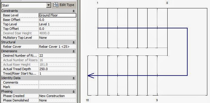
  • Start with placing two runs, and it will create the first landing.  Note that Revit numbers the first and last riser on each run
  • Then place another run starting on top of the lowest run (this was not possible prior to Revit v2013);  it starts getting confusing already - it tells you how many risers are remaining to finish but its hard to distinguish visually where you are at

  • The top run will display riser numbers when selected, but only after it is placed - this helps you distinguish which run you have selected
  • It is much easier to see what is happening in section, elevation or 3D, although riser numbers are not displayed; you do get the shape handles in section/elevation
  • When you finish the stair, you will get the inevitable warning message as Revit creates the railings (the stair itself is fine)
  • Revit will go ahead and create the railings, with only the usual glitches as it tries vainly to go around the inside corners
 
  • The reason for the warning is that the automatically created railings contain sketch lines that overlap each other.  Revit would not normally allow this to happen - certainly if you tried to sketch it that way yourself it would not let you.
This warning message is a bugbear of the new Revit stair by component tools.  The software developers apparently knew that this would happen because Revit allows the stair and its railings to break the normal rules.  As users, we have assumed that the new stair tool was part one of an update process and that new railing tools would follow, and resolve the problem - but we have not seen any new railing tools yet.  We live in hope!

So, Revit will create these "railings with warnings" but woe betide if you need to modify the railing sketch lines - it is almost impossible to untangle the overlapping lines.

If you do need to modify the railing, refer to the next post  Multistorey Railings - Story 2.


Multi-Level Multistorey Stairs

Once you start going past three flights and over multiple building storeys it gets more interesting.  There are two approaches to defining the overall stair height and riser height - the options are somewhat akin in principle to the Array command in Revit:
I will refer to them as "Define Second Storey" and "Define Last Storey" techniques, so the comparison with the Array command makes sense.  In the examples shown here, I will stick to two runs per storey, to keep it simpler.  What varies between the two techniques is the setting for 'Top Level', and as a result the overall desired stair height and desired number of risers.

If all your building storeys are the same height, it should be fairly straightforward, because riser heights would be identical for the entire stair.  However, if some storey heights vary, you may run into trouble, as seen below.  Both techniques will not allow you to vary riser heights for different storeys, so that aligning landings to storey levels may be a problem.

Define Second Storey Technique
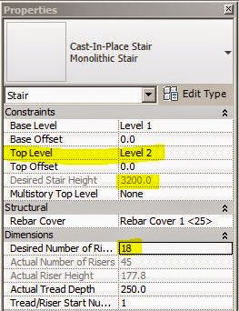
For the Top Level of the stair, you can define the upper level of the first building storey that the stair spans, even though you intend for the stair to keep going above that level.  Revit will calculate the riser height and number of risers for that building storey only.
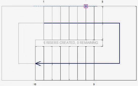
  • After placing the first couple of stair runs, you will reach the desired number of risers;  Revit lets you keep adding more runs - when you start placing more overlapping runs, the automatic riser numbers in plan will display the Desired Number of Risers + the additional number, which can be a little confusing
  •  Just for the record, the size of these automatic riser numbers is controlled by the view scale - if you want to be able to read them, just bump up the scale temporarily
  • The riser height will be constant for every run - this means that on the runs above the defined Top Level, you may not be able to align the stair exactly with levels where upper storey heights vary
  • Once the stair is complete, you will be able to label the step numbers using the "Stair Tread Number" annotation tool.  The numbers will display the correct riser number within the whole stair rather than the "Desired +" that you get with the automatic riser numbers.  This is a different result to method 1 (virtual upper level runs created using the Multistory Top Level setting) where the upper levels cannot be numbered at all

Define Last Storey Technique
For the Top Level of the stair, you could define the highest level of the stair.  Revit will calculate the riser height and number of risers for the whole stair
  • The riser height will again be constant for every run - this means that intermediate landings may not be able to align exactly with middle levels where any storey heights vary
  •  The automatic riser numbers in plan will be the actual number within the whole stair

Once you complete the stair, you will get the inevitable warning message
You can ignore this message if you never intend to edit the railing.  If you do want to edit it then refer to the next post about Multistorey Railings - Story 2

Monday, 10 February 2014

Revit Multistorey Railings - Story 1


[Edit: Revit 2018 has a new method for creating multistorey stairs & railings, so the issues described here will not be relevant once you upgrade to v2018;  if you are using v2017 or earlier, read on]

Here is a curious story to tell:  This is a description of how to manage railings on a multistorey stair that has been created using the "Multistory Top Level" stair property in Revit (Method 1 in my previous post), and where you have incorporated intermediate landings on each building level of the stair.  The resulting railing will be a single closed loop - both inside and outside joined together. 

The description below assumes that you followed the steps in the previous blog post  to get to this stage.  If your multistorey stair does not include landings at the storey levels (maybe you used floor slabs instead), none of this applies.

Edit Railing
If you try to edit the railing to get rid of the section running across the landing/run junction or the outside edge of the landing, you will run into problems in Railing edit mode

After you delete the unwanted lines and then finish the sketch it will give an error message – it requires a single continuous chain of sketch lines, not a loop within a loop (even if you remove all overlapping lines)


To solve this the railing needs to be first separated into two parts. This can be done by two different methods:
1.  You could duplicate the single railing and then edit each one separately, stripping them back to an inner and an outer railing (Process not described here).
2.  Alternatively, take a few steps back in the stair creation process, to edit the railings before you delete the temporary top flight:

  • Edit the outside railing (because of the top run there are two separate railings). 
  • Delete the segment associated with the extra run

  • Make sure there is a break in the loop by dragging the end of the landing rail line away from the first run line; the gap must be at least 32mm otherwise the lines will automatically rejoin! (That is about 1 ¼ inches in that quaint imperial system used in the USA).

  • NB. If you want the sloping section of rail to extend one tread beyond the lowest riser (common practise), then you need to extend that line by one tread depth before making the 32mm gap.  It may give you a slope warning, but it is not clear why because the railing will be parallel to the flight
  • One method to stop that warning is to make the sketch line overrun dimension just short of a tread depth – by 1mm say (for a 250mm tread, the railing sketch line should extend 249mm past the lowest riser)
  • Then you need to do something similar for the inside loop railing – delete unwanted segments and make a gap. You might again want to extend the sloping rail line by one tread (minus 1mm), and then make the gap in the short landing line

  • Another alternative is to extend the short landing line by at least 32mm, and leave a gap of 1mm to avoid the sloping railing warning. The best option depends on how your rail is defined relative to the sketch line location and how you want the join to work
  • Finish the railing sketch

  • Edit the stair to delete the top flight – the railings should now be separate. NB. This process does break the automatic nature of the railing sketch – it will no longer update when the stair changes

Once you make the stair multistorey again, the railings should behave better. The small gaps may not be perfect but they are a whole lot better than the junctions that Revit makes normally

If you don’t want the railings to run across the back of the stair landings (eg. doors onto landing), you can edit the railing to remove segments but you'll lose the side railing of the landing (because you need a continuous chain of sketch lines in the railing)

Then you need to add a new railing to the landing sides: host it on the stair if you want it to be the same on both levels (it will become multistorey if the stair is); or host it by level if you want different railings on each landing
 

Watch out for the “Tread/Stringer Offset property for the railing so that it will align properly with the other railings (defaults are different for automatic railings and manually created railings)

Non-multistorey railings must be hosted by level, not on the stair – that way they can be different on each level

However, if you find all this is too fiddly, or else you need the top landing to be different then you may need to try Method 2 for multistorey stairs.
You could also lobby Autodesk to fix the railing tool so that it works better with the new stair by component tool!  Maybe one day we won't have to invent these horrible clunky workarounds.