BILT Speaker

BILT Speaker
RevitCat - Revit Consultant
Showing posts with label calculation. Show all posts

Monday, 20 April 2020

System Volume Parameter in Generic Category Families

 Here in New South Wales, Australia, we have a planning requirement (SEPP65) to provide a certain amount of storage in multi-unit residential developments.  Some of that storage can be in the apartment itself, and some can be in storage cages/cupboards in the basement.

The storage has to be calculated by volume per apartment - this means that we have to create schedules that combine the storage cupboards in apartments with the cages in the basement.  Thus we need to create objects of different shapes and sizes in the model.

There are several ways to calculate the volumes from these objects, but surely the simplest way would be to use Revit's automatic volume calculation properties?

System Volume Property

You would think that Revit would be able to report back the volume of any object in your model.  It is a database, right?

It turns out that it can do so, to a very limited extent - and of course that leads to restrictions and frustrations.

It seems that only cetain category objects can report their volume, and then there may be further restrictions on scheduling or tagging:

By Category

  • Many of the system families do have a "Volume" property

  • But you would not want to create storage cages or cupboards by mis-using those categories?  No, you would not!
  • Logically you would use the Casework category for cupboards - but sadly that category does not have a volume property.
  • The same applies for most loadable family categories.

  • You could use the Mass category, but that is not sensible either, because that should be reserved for creating building massing models - if you start mis-using that category it will surely make life difficult (not least with visibility issues).

  • Rooms do have volume properties, although that can depend on project settings - see below.
  • Rooms are also not an ideal way to model such things as high-level storage cupboards!

  •  That leaves us with one last option (that I know of):  the Generic category.
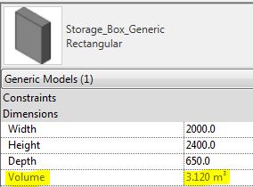
  • For many years in Revit, generic families did report a Volume property (automatically calculated from the volume of all solid objects in the family).
  • However, it was not originally possible to schedule this property
 
  • In Revit 2014, Autodesk enabled the ability to schedule this Volume property.
  • This was one of my few successes with lobbying Autodesk to include one small new feature in Revit, that would make a big difference to us.
  • Sadly they ignored my pleas to also enable this property to be tagged.

Generic Families

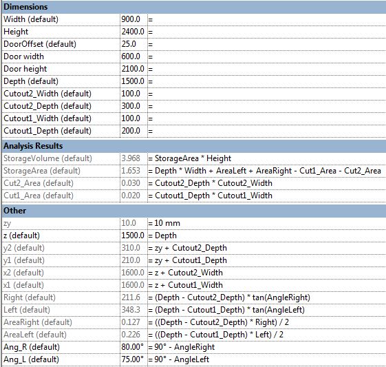
Prior to v2014, we created a range of storage families that did the volume calculations as formulas within the families - so that we could schedule and tag the volumes.

When it comes to basement storage cages, the shapes often become quite complex as they have to wrap around columns or need angled sides.


This led to some quite complex formulas that needed to take into account optional cutouts to the shapes, and to allow for overlapping cutouts.


Fortunately all these calculations became redundant with v2014, as we can now use the system calculated "Volume" parameter to schedule storage volumes.

Except . . . . . When a project requires the storage to be tagged on drawings.

Room Volumes

Rooms do have the ability to calculate and report their volume, and it may be easier to create basement storage cages as rooms with cage walls to enclose them.  This would allow any shaped area without having to create a range of families.


However, this becomes problemmatic when you need to create one schedule that combines the basement storage cages (Rooms) with in apartment storage cupboards (Generic category families).

Room volume calculations also have some quirks, that depend on project-wide settings:

  • Rooms have a height property - this is used for the system calculated volume.
  • However, it will not work if Rooms are set to only calculate Areas (not Volume)
  • This project-wide setting is generally recommended as it makes the project performance noticeably faster - the menu even tells you that (and it is true)

  • If you enable Areas and Volume calculation you will get the volumes being reported, but a slower project.
  • If you need to do this anyway, then it is no extra overhead for calculating room storage.


Room Volumes are calculated at Wall Finish, regardless of the Room Area settings.
  • This can be complicated if you need room areas to be calculated to wall centrelines.
  • More on this in another blog post . . . .

Wednesday, 23 August 2017

Scheduling Global Parameters in Revit

Revit is all about data and displaying or extracting that data.  So, you'd think that when a new Revit feature  is added, like Global Parameters, you should be able to schedule them?
Wrong!  You cannot directly schedule or tag Global Parameters in Revit.

However, I have devised a workaround (NB. this won't work on Revit 2016 R2):

Example 1 - Reporting Dimensions

In this example there are several sloping ceilings.  Each ceiling has a built-in property 'Height Offset From Level', which represents the height of the base of the ceiling slope.  This can easily be scheduled.  It is not so easy to schedule the height of the top of the ceiling slope - unless you use global parameters:

Step 1 - Reporting Dimensions

  • In a section view, add a dimension from the level to the top end of the sloping ceiling
  • Associate this to a global parameter
  • Make it a reporting parameter
 

  • Repeat this step for each sloping ceiling


Step 2 - Project Parameters

  •  Create a new instance project parameter called 'Ceiling Top Height'
    • Make it a length type
    • Apply it to the ceiling category
    • Give it a meaningful tooltip
  •  Each ceiling will now have that property, albeit blank


Step 3 - Associating Global parameters

The Project parameter properties of individual ceiling elements then need to be associated to the relevant global parameters (reporting dimensions):


  • This obviously means that one global parameter is required for each ceiling, which could become tedious for many elements - but this a workaround, after all.

Step 4 - Create the Schedule

A schedule can be created to display this information:
  • A ceiling schedule could be created, showing the built-in height parameters and the project parameter with associated global parameter


Example 2 - Area Calculations and WC Numbers

Step 1 - Global Parameters

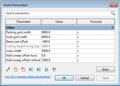
Create your global parameters, with formulas as required.  In this example, global parameters are being used to calculate the number of toilets required for a community hall, where the statutory regulations require a certain number depending on the floor area of the hall:


  • There are two reporting parameter dimensions for room width and length.  
  • These are used to calculate a room area - this is an extra step to be taken because even though Revit gives us room areas automatically, we are not able to associate areas as reporting parameters, so we can't use the system Area property (except as a check on the calculation)
  • There is a user defined "Area per WC" - which is set as 1 WC required per every 30 square metres of the hall area.  This value can be changed later.
  • To establish the number of required WCs, a simple calculation is done:
    Hall Area / Area per WC
    This is an integer parameter so it always gives a whole number;  however, you could make the formula a bit more complicated so it always rounds up to the next integer
  • There is another check formula that sets the minimum number of WCs to be 2 - this is partly because arrays will only accept 2 as a minimum.  There is an 'array workaround' if the minimum really needs to be 1, but that is not shown here.


Step 2 - Project Parameters

The trick for being able to schedule and tag global parameters is again to use an intermediary - namely Project Parameters:
  • As many project parameters are created as you need for scheduling/tagging global parameters
  • They are defined for the categories to be scheduled - in this example it will be for both rooms and generic categories
  • 'Area Calculated' is added to the room category so that it can be scheduled and tagged
  • It must be a shared parameter for tagging;  if you want to apply it to just one category and only schedule (not tag), you might get away with it not being shared;  for multiple category schedules it needs to be a shared parameter.

  •  'WC Numbers' is an integer parameter added to both the room and generic categories - for rooms it is just for schedules/tags;  for generic categories it is being used to drive the model - number of WCs in the array

Step 3 - Associating Global parameters

The Project parameter properties of individual elements then need to be associated to the relevant global parameters:
  • The room element for the hall has its 'Area Calculated' property associated to the 'AreaCalc' global parameter
  • Its 'WC Numbers' property is associated to the 'WCNumCalc' global parameter

  • The WC cubicle component has a family property for the 'Number of WC Cubicles', which is used to control the number in the array.  This is associated to the 'WCNumCalc' global parameter - so that when the hall area changes, the global parameters recalculate the number of WCs and push that change into the cubicle array component..
  • NB. It is not possible to associate a global parameter directly to an array number in the project environment, so the array has to be built into the family - another workaround.

Step 4 - Create the Schedule

Schedules can be created in a number of ways to display this information:
  • A room schedule could be created, which shows the contents of the room


  • A better way to achieve this is to create a multi-category schedule that includes one element in the required room (Hall) and also the WC cubicles in the other rooms
  • Room properties can then be added for each element - in particular the project parameters for the hall room
  • The one element in the room 'Hall' needs to be listed in order to display the associated global parameter values of the room (Calculated Area & Required WC numbers), even if we don't want to schedule that element itself. This is because a Revit multi-category schedule cannot contain rooms as one of the categories - only the room properties of other category elements.
  • In this example, the schedule needs to be filtered to restrict it to just show generic category elements (WCs) plus the category of the element in the hall (a door in this case, but it could be anything); and then further filtered to get only the relevant ones listing

  • The fields from Rooms and Count, can be renamed to indicate required and supplied WC numbers

Conclusion

These are only two specific examples of how global parameter data can be scheduled and displayed.  Of course it is unlikely to suit your exact requirements but it should demonstrate the principles to be applied to different situations.

Friday, 15 April 2016

What's New in Revit 2017

As Steve Stafford has compiled a comprehensive list of new Revit 2017 features over on OpEd, I will not write a list here.  Instead I will comment on a few features - especially since the Autodesk Help files are so sparse on detail.  We all need to know the benefits and shortcomings of each new feature.

I have previously commented on v2016 R2 features (in this link), which are obviously now included in v2017.

New in Revit 2017 (selected features)

Global Parameters

My initial description of Global Parameters as introduced in v2016 R2  is only relevant if you are still using v2016R2.
For more details on Global Parameters in v2017 click here

Improvements in v2017 are more significant than I first thought - they include:
  • Type Parameters can now be linked to Global Parameters (GPs)
  • Assign global parameters to groups within the list in the GP dialog box
  • Reorder GPs in the list
  • Filter a schedule by parameters that have GP associations - this should be invaluable for tracking down all those associations that are making unexpected changes to your model!
  • Show Label in View - hopefully useful, but that 'Cannot find view. . .' message is a worry when looking for other warnings and issues, so I don't know how useful it will actually be?
  • Transfer GPs between projects
All of these are very welcome additions to this exciting new feature.  However, we are still missing the ability to associate GPs directly to many system properties, although this has improved in v2017.

More on this . . . . Global Parameters in v2017 click here

Schedule Templates

Schedule templates now include parameters for Fields, Filters, Sorting/Grouping and formatting - previously it was only the Appearance that could be included in a schedule template.  This sounds wonderful, but in my opinion it is very dangerous in the way it has been implemented:
If you apply a schedule template to an existing schedule, it will entirely replace all your fields, filters, sorting, formatting.  This means that if you had all sorts of complex calculation fields in the original schedule, they will be destroyed and lost forever!  It is all or nothing - you cannot just include some things in the template without the others (eg. filters & formatting only, without fields).  I understand that it would be tricky to separate out what is contained in each template as the fields are interrelated - ie. it has to exist in the field list in order to be formatted or used in a filter.  However, I think we should have had a cleverer implementation that allowed us more flexibility and safer control.
Unless the final rollout of v2017 has changed since I last tested, there is no ability to "overwrite or append" to a schedule where fields already exist - it just replaces without so much as a 'by your leave'.  Mark my words:  There will be tears before bedtime!

So, a word of caution:  plan how you use this very, very carefully - set up some complex scheduling and save it as a template first so you don't lose the calculations!

Combine Schedule Fields

Steve Stafford described this very well in his blog over on OpEd, so I won't replicate the description.  While this is a great step in the right direction, it will only allow you to combine or 'concatenate' parameters in the actual schedule output.  This means that combined parameters are not visible in the element properties dialog, nor can you tag them, nor will they be exported (unless you export just the schedule).  So if you need to actually populate element properties with combined parameters, you will still need to use Dynamo, API or a third party add-in.

Calculations in Annotation Tags

Another very welcome addition to tagging capabilities, but again this comes with some serious limitations:   The calculations are defined in the tag in family editor - this means that you have to replicate identical calculations in a schedule if you want to see the same results in both schedules and tags.  That is asking for user errors.  In addition, when working in the tag, you will not be able to access any Project Parameters, Schedule Parameters, and some System Parameters only visible in projects (such as offset from Level) - depending on the category, some system parameters are available in tags, some are not.  eg. Base Offset for wall is not available; but Sill Height is available for windows.  This means that we will need to use more Shared Parameters instead of non-shared Project Parameters, although that won't solve the issue of System parameters - of course shared parameters can't be used in all situations anyway.

This is a good first step to fixing a problem with tags, but it needs to go much further by allowing us to embed the calculations back into the actual elements so they only need to be done once then be available everywhere (properties, schedule, tag, export).

Tangency Locks

[Edit] When editing a sketch in the family editor, we can now 'lock' the join between a line and an arc to maintain it as a tangent join.  I am very happy about this new feature - I have long struggled to control arcs in Revit.  Most of the time, in simple situations it works well.
In this example, the end of one line is adjusted so the line changes angle - and the arc is extended to maintain the tangency.

However, it needs to be used with a little caution until we all understand exactly how it works and what it does to overall sketches.  I tested the simple sketch above a little more by adding parameters to the radii, and it had some unexpected consequences.  Previously, if you moved/rotated a line that had a tangent arc at its end, it often just broke the tangency.  Now it can possibly have a knock-on effect all along the sketch:  It can completely move lines on the sketch way along the chain beyond the tancency lock.

 When the end of the right hand line is moved in, the radii change, and the left hand line moves in
When the end of the right hand line is moved out, the radii increase, and the left hand line moves left


Move the end of the line a bit further and the sketch goes crazy:


As the tangencies cannot be broken, something else has to give!  To prevent this sort of behaviour, every line would have to be dimensioned/constrained in location and angle.

This means that we will need to put more thought into controlling the whole sketch - not necessarily a bad thing, but it could cause problems if you add tangency locks to old sketches.  We have often been lazy in the past because we could get away without adding dimensions or constraints to many lines in a sketch - Revit would do the work for us with implied constraints (lines generally stayed parallel even if the moved, and they locked themselves to nearby reference planes).

More on this - click here, as it requires a careful analysis . . . .

Elevation Depth Cueing

I have done some testing of this new feature - read about Depth Cueing here for more detail.  Read about depth cueing on angled/curved walls here.
It seems that in order to display receding distance in Elevation and Section views in Revit, Autodesk have chosen the easy path of making lines lighter the further they are away, rather than allowing control of line weights, which is the old conventional drafting method.  It certainly does achieve an effect of 'distance' even if it has some limitations (like not working with line weights or anything worked over using the Linework tool).  You may not like the method it uses or the simple controls which are easy to use but will probably make consistent output very hard to achieve.  You may also not like printing all your elevations using the raster driver, although I hear that it is less of an issue than it used to be.


Installing Revit 2017

Installing Revit 2017 using a download is a whole new adventure (not a pleasant one)
Read about download/installation here - not much fun at all
Read about installing from DVD media here - a much pleasanter experience

New Revit Icon

I like the new Revit icon - it looks less like folded paper, and more like a carved sculpture that you could not possibly make using the massing tool, however hard you try.  I like to have a different icon each release so that you can easily tell which version is showing up in your windows taskbar - especially if you have multiple versions open.

Conclusion

This post is not meant to sound negative - I am just warning you about issues with new features that sound too good to be true!  They all have value but need to be treated with care.

Is Revit 2017 good value for all that subscription money you payout?  You might not think so, but I could not possibly comment.  For an architect there is not a huge amount to be excited about - many new features are relevant to other disciplines or might be of more benefit to others downstream.

There are no big standout features in v2017 that we must have now, so I will be a little cautious about rushing into the upgrade, particularly as there are a lot of goodies to be had in v2016 R2 already, without the pain of another file format change.  When you add the list of v2017 features to those in v2016 R2, it is a reasonable number of small additions and tweaks - but there are so many, many more to address, let alone some of the underlying structural changes that need to happen in order for us to be able to use Revit efficiently.

Saturday, 27 April 2013

Revit's most hidden commands

Recently I did a Revit demo of divided paths and repeaters.  Afterwards someone said they had spent a day trying to figure out one simple thing I showed - they searched everywhere, including Youtube for videos but could not find out how to control divided path node visibility in a project.  That got me thinking about some really hidden away commands and features in Revit that are not at all intuitive and are not clearly explained in the Wikihelp - so here are a couple of them:

Divided Path & Divided Surface Node Visibility

When you are in the Conceptual Massing Environment (CME) in Revit (Mass family, In-Place mass, Adaptive Component, Pattern-based family), there are two commands for dividing elements:   Divide Path & Divide Surface.
They behave slightly differently but have a common purpose and methodology as well as common problems.

Divided Path

When a linear element (line, arc, spline etc) is selected, a command becomes available: "Divide Path" - this does not affect the original element but places a new element on top, which is divided into a specified number of segments delineated by nodes.
These nodes show as blue dots, and can be used to snap onto.  There is no way to control the size or colour of the nodes - it is hard-coded into Revit.  The visibility of the nodes is also hard to control;  in fact, in the project environment they cannot be controlled at all - if they were visible in the family when it was loaded, then they will always be visible in the project, which can be very frustrating.  Don't waste your time looking for settings in "Visibility Graphics" or anywhere else in the project settings - you have to go back and edit the family to hide them:
In the family environment, select the divided path.  On the menu, it should display a panel called "Path Representation";  on the bottom right corner of the menu panel is a tiny black arrow.
Click on the arrow and it will open a Path Representation dialog box


This is where you can turn on or off the node visibility. Then you can save the family and load it into a project again.

Divided Surface

This works in a similar way and has the same visibility control problems, but of course it is inconsistent with the divided path in several ways:
1.   By default the nodes on a divided path are visible;  on a divided surface they are not, so you have to turn them on to see them!

2.  The number on a divided path refers to the number of nodes;  on a surface it refers to the number of segments - thus the same number would result in one extra node on a surface relative to a path

3. Surface representation has additional options related to grids, lines and patterns.

However, if  all three checkboxes are unticked, it still displays the original surface and it seems that there is no way to turn off its visibility - ie the "Original Surface" checkbox only works when one or both of the other two boxes  are ticked (Nodes or UV Grids and Intersect Lines).  The only way I could figure to hide it is to tick the "Original Surface" checkbox, which enables the material settings so that you can make its material transparent.

Hopefully this will save someone else from spending all day searching how to control node visibility.

Room Area Calculation Height

This one catches me out every time I want to change it - I have to search the internet for clues on how to control what height room area calculations are made.  This might not seem a big deal but when you have a split level building it certainly becomes vital, as room areas can be calculated for the wrong floor, or not at all.  It can also be a problem if some of your walls start or stop at unusual heights.
In this example the room on the left displays its hatching and area correctly.  The one on the right does not - the difference here is that one of the walls on the right has a base offset of 200mm.  By default the room area calculation is done at zero height above the floor level, so Revit considers the room to be not enclosed.

How do you change this?  After much head-scratching you might eventually figure out that the setting is not a project setting, nor a room setting but is in fact a property of the Level that the room is placed on.  If you go to a section or elevation view and select the level, it will display the properties.

One of the properties is "Computation Height".   Change the value of this to 300mm (above the base offset of the wall), and the room is now enclosed properly.
Pretty obscure huh?  You can argue whether this is the right way to control the area calculation as it certainly gives flexibility to have different values for each level.
But there is no doubting that this has to be one of the most hidden away settings in Revit - who would think to look there?  Who would remember this setting without being traumatised by spending hours or days trying to troubleshoot why a room is not properly enclosed?