BILT Speaker

BILT Speaker
RevitCat - Revit Consultant
Showing posts with label room. Show all posts

Wednesday, 1 July 2020

Analysis of Slanted Walls with Rooms in Revit 2021

Following on from my Analysis of Slanted Walls in Revit 2021, I want to see how they interact with Rooms.

Room Enclosure

The first thing to study with slanted walls is how they behave when enclosing room elements.

  • With a normal wall, when you raise the base offset above the base constraint level, you may get this warning:
    • "Room is not in a properly enclosed region"
  • This does depend on the computation height of the room see below)

  • Note that if the new wall property "Cross-Section" is set to "Slanted", this does not happen (even when the wall angle is set to zero (effectively a vertical wall):

I have no idea if this was intentional in the design of the new slanted wall feature?  However it is now inconsistent with vertical wall behaviour.
This may be good or bad:
  • Bad - it is inconsistent behaviour.  Another exception to the rule to learn
  • Good - this gives us a new workaround for when you need to raise wall base heights but cannot change the computation height for rooms.
NB. Just to complicate this issue, this behaviour only occurs when the Volume Computation settings are by "Areas only"
  • If you change the setting to by "Area and Volumes" it reverts to not enclosing the room.
  • You will now have to teach people an "Exception to the exception" rule.


Vertical Room Extent Enclosure

Revit Room elements have a Base Level and Upper Limits (with offsets).  This normally controls their vertical extents.


Revit rooms can have their vertical extents enclosed by certain elements, thus over-riding their vertical extent properties - in certain situations.  By default, sloping elements probably will not affect the vertical room extents.
  • The Room & Volume settings are set to "Areas only" by default


  • If the Volume settings are changed to "Areas and Volumes" then vertical extents can be over-ridden by elements that intersect their geometry


  • These elements must be of specific categories (eg. Floor, roof, ceiling)
  • They must have their "Room-Bounding" property ticked
The room height (or base) may be cropped by the room-bounding element, but the room will not extend beyond the vertical extent properties.

Slanted Wall Room Enclosure

The new ability to slant walls in Revit 2021 has implications on how the horizontal room extents behave.
If we reset the base offset of a slanted wall to zero, and change the angle it can be seen that effects on the horizontal room extents are more complicated than vertical.
  • Horizontal room extents are always calculated by bounding elements, not by properties - quite unlike the vertical extents.
  • The volume computation settings may also affect this;
  • The wall pivot point will affect the room extents;
  • In addition, the Wall Base Offset and Computation Heights may also be relevant.
  • If the wall pivot point is the centre of the wall, as noted previously, the bottom corner of the wall moves when the angle changes (because wall thickness changes in plan).
  • This also changes the room extents - as can be seen below:


  • If the wall is slanted in towards the room, and the volume computation is by "Area Only" the room extents will align with the bottom corner of the wall, but will not be cropped by the wall

  • When the volume computation is changed to "Area and Volume" the room extents will align with the room and will be cropped by the wall (providing it is Room-Bounding)

If the Base Offset of the wall is raised above the base Level, the room extents are controlled not by the bottom corner of the wall but by the bottom corner of where the wall would be if it was set to Vertical - ie. where the wall face would meet the level if projected down.
  • That is another exception to teach

  • If the wall Location Line is not on the wall face (room side), but say on the wall centreline, there is another exception to an exception:
    • The room extents line up with the "bottom corner of where the wall would be if it was set to Vertical - this does not align with projecting the wall face down to the level"

  • By making the angle more extreme it can be seen more clearly

However, there is an exception to an exception to an exception:

  • If the volume computation is changed to "Area and Volume" and the Computation Height is below the Wall Offset height, the room is no longer enclosed - and you will get a warning message.


Computation Height

Things get even more complicated when you change the Computation Height.

You may remember that the Room extents are calculated at a certain height above the level on which the room is placed.  By default this height is zero - but your BIM Manager may have changed this in your project template.
  • The Computation Height is a property of the Level (not the room element).
  • This means that all rooms on a given level are calculated at the same height
  • If the volume computation is set to "Areas only" the room area will be calculated where the wall meets the computation height plane
  • The room will not be cropped in section - and your drawing will look terrible if you have a colour scheme in section.
  • If the volume computation is changed to "Area and Volume" the room is cropped in section and the volume is calculated
  • However, it only crops the room volume where the wall overlaps, which will give an accurate area but the wrong volume - as it does not extend the room outwards beyond the point where wall and computation plane meet.
At first glance this seems consistent with what happens when a sloping roof or floor meets a room volume - however, this situation is entirely different:
  • In the case of vertical extents the room height has properties to control that cutoff line
    • The user can intervene by changing the properties.
  • In the case of plan extents, they should be automatically calculated to the full extents of the volume enclosed
    • The user has no ability to override the extents.

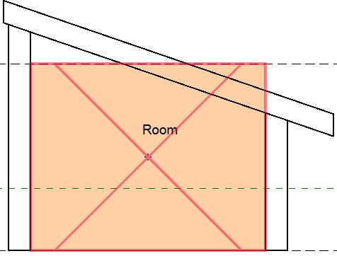
If you have a combination of the following, I can't begin to explain what Revit will do - just look at the image to figure it out:
  • Wall Base Offset
  • Raised Computation Height
  • Room volume computation by "Area and Volume"
  • Slanted wall
  • Wall Location Line set to Centreline


Conclusion

I would hate to be teaching a new Revit User about all these inconsistencies and exceptions.

I believe that it would help the situation a lot if the following two problems were fixed:

1.  Pivot point of slanting walls should be from the actual base level of the wall, not from where the slanted wall edge meets the level.  Refer to Analysis of Slanted Walls in Revit 2021,

2.  When the volume computation is set to "Area and Volume" the room should be cropped in section for the whole height of a slanted wall - extending inwards and outwards from the computation height plane.  This would give more accurate volumes and would look a whole lot better on section views that have room colour schemes.


Monday, 20 April 2020

System Volume Parameter in Generic Category Families

 Here in New South Wales, Australia, we have a planning requirement (SEPP65) to provide a certain amount of storage in multi-unit residential developments.  Some of that storage can be in the apartment itself, and some can be in storage cages/cupboards in the basement.

The storage has to be calculated by volume per apartment - this means that we have to create schedules that combine the storage cupboards in apartments with the cages in the basement.  Thus we need to create objects of different shapes and sizes in the model.

There are several ways to calculate the volumes from these objects, but surely the simplest way would be to use Revit's automatic volume calculation properties?

System Volume Property

You would think that Revit would be able to report back the volume of any object in your model.  It is a database, right?

It turns out that it can do so, to a very limited extent - and of course that leads to restrictions and frustrations.

It seems that only cetain category objects can report their volume, and then there may be further restrictions on scheduling or tagging:

By Category

  • Many of the system families do have a "Volume" property

  • But you would not want to create storage cages or cupboards by mis-using those categories?  No, you would not!
  • Logically you would use the Casework category for cupboards - but sadly that category does not have a volume property.
  • The same applies for most loadable family categories.

  • You could use the Mass category, but that is not sensible either, because that should be reserved for creating building massing models - if you start mis-using that category it will surely make life difficult (not least with visibility issues).

  • Rooms do have volume properties, although that can depend on project settings - see below.
  • Rooms are also not an ideal way to model such things as high-level storage cupboards!

  •  That leaves us with one last option (that I know of):  the Generic category.
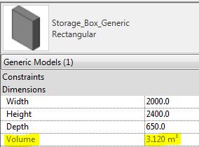
  • For many years in Revit, generic families did report a Volume property (automatically calculated from the volume of all solid objects in the family).
  • However, it was not originally possible to schedule this property
 
  • In Revit 2014, Autodesk enabled the ability to schedule this Volume property.
  • This was one of my few successes with lobbying Autodesk to include one small new feature in Revit, that would make a big difference to us.
  • Sadly they ignored my pleas to also enable this property to be tagged.

Generic Families

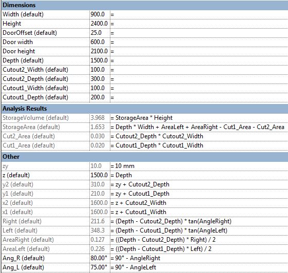
Prior to v2014, we created a range of storage families that did the volume calculations as formulas within the families - so that we could schedule and tag the volumes.

When it comes to basement storage cages, the shapes often become quite complex as they have to wrap around columns or need angled sides.


This led to some quite complex formulas that needed to take into account optional cutouts to the shapes, and to allow for overlapping cutouts.


Fortunately all these calculations became redundant with v2014, as we can now use the system calculated "Volume" parameter to schedule storage volumes.

Except . . . . . When a project requires the storage to be tagged on drawings.

Room Volumes

Rooms do have the ability to calculate and report their volume, and it may be easier to create basement storage cages as rooms with cage walls to enclose them.  This would allow any shaped area without having to create a range of families.


However, this becomes problemmatic when you need to create one schedule that combines the basement storage cages (Rooms) with in apartment storage cupboards (Generic category families).

Room volume calculations also have some quirks, that depend on project-wide settings:

  • Rooms have a height property - this is used for the system calculated volume.
  • However, it will not work if Rooms are set to only calculate Areas (not Volume)
  • This project-wide setting is generally recommended as it makes the project performance noticeably faster - the menu even tells you that (and it is true)

  • If you enable Areas and Volume calculation you will get the volumes being reported, but a slower project.
  • If you need to do this anyway, then it is no extra overhead for calculating room storage.


Room Volumes are calculated at Wall Finish, regardless of the Room Area settings.
  • This can be complicated if you need room areas to be calculated to wall centrelines.
  • More on this in another blog post . . . .

Monday, 3 February 2020

Room Bounding Structural Column Materials in Revit


I recently discovered yet another obscure, hidden away setting in Revit - when I was investigating the "Room Bounding" property of different elements.

It seems that some structural columns have a "Room Bounding" property - but not all.
This has to be one of the weirdest, arbitrary decisions made by the Revit programmers:

Material for Model Behaviour

Structural columns have a weird property - so obscure and arcane, not to mention hidden away.
'Material for Model Behavior'

This property that can only be set in the Family Editor – in ‘Family Category and Parameters’: ‘Material for Model Behaviour’.


It can be one of 5 settings, each of which enables different properties and behaviour in the model:
  • Steel
  • Concrete
  • Precast Concrete
  • Wood
  • Other
Depending on which one you choose, it will enable properties in the family.
  • Steel has Connection properties
  • Concrete & Other have Rebar properties
 

These settings are hidden away behind the 'Family Category and Parameters' settings - in the project there is no way to tell which setting the family has, apart from the specific properties displayed.

You would have thought that this only affects structural engineers?

But wait.  It affects architects too . . . . .
  • Concrete has ‘Room Bounding’ properties (it is the only one that does)


Why, oh why are wood and precast concrete not room-bounding?  There are a huge number of timber structures around the world that provide perfectly good enclosures.
Wouldn't it just have been easier to make all columns potentially enclose rooms, instead of hard-coding someone's bizarre ideas about how a building might work?

Room-Bounding

When working in a project, and you discover that a 'Room' is not enclosed when you expect it to be, this is one of many things to check.
There are some other quirky Room-Bounding behaviours in Revit, to be detailed later  . . .

Monday, 6 January 2020

Preventing Levels and Internal Origins appearing in new 3D Views

How many times have you seen a Revit 3D view obliterated by Scope Boxes?
Well, now we have Levels visible in 3D (2019) and Internal Origins in 3D (2020.2), which can also be visible by default.


There is a simple solution to prevent this happening:

Default 3D View

Typically, when you create a new 3D view, it has almost all categories visible, including Scope Boxes, Levels, Room Separation lines, Base Points and now Internal Origins. These can be very annoying in 3D views - particularly the Origins in perspectives.

Here is a procedure to prevent this:

  • Go to a default 3D view 
  • In Visibility Graphics, turn off the visibility for Room Separation lines in model categories
 

  •  Turn off all three Origin sub-categories (Internal Origins visible in 3D from v2020.2)

  • Turn off the Scope Boxes and Levels category (Levels are visible in 3D from v2019); 
  • [Optional] turn off other datum and view control categories like grids, reference lines, sections, elevations (in case they become visible in 3D views in the future)
  • Create a new View Template from the 3D view – called ‘3D Default – do not delete’- [NB. “do not delete” part of the name is to prevent accidental changes later]
  • Untick all the ‘Include’ boxes except for V/G Overrides Model & Annotation

  • Click OK to close and save the View Template
  • Go to the Type properties of the 3D view

  • Set the ‘View Template applied to new views’ property as your new 3D Default view template 
  • Untick the ‘New views are dependent on template’ property – this means it just turns off those categories, without permanently applying a view template;


  • You will subsequently be able to change other category visibilities;
  • All new 3D views and perspective views will have those categories turned off by default (scope boxes, Levels, Origins,  Room Separation lines etc).
This should obviously be set up in your project template as well as all current projects.


Friday, 30 August 2019

Travel Path Update in Revit 2020.1

Following on from my posts about Revit 2020 on Path of Travel and Follow Up :

With the release of Revit 2020.1, we have been given four minor improvements to the new (2020) 'Path of Travel' feature in Revit.  Welcome as they are, these improvements do not address any of the fundamental shortcomings of the tool, which seems like a missed opportunity:
  1. Start and End Points of travel paths can be dragged.
  2. Reveal Obstacles toggle.
  3. To and From Room properties have been enabled (these were previously just blank instance properties in 2020).
  4. Two new Dynamo nodes for Travel Paths (presumably new API capabilities allow this?)

Start and End Points

If you select an existing 'Path of Travel' element (which behaves like a polyline detail line) it now displays a blue grip-handle dot at each end.
  • Select the grip-handle and drag it to a new location - while doing so, Revit displays a moving straight line directly between the cursor and the other end of the path.

  • Once you let go the grip-handle in its new location, Revit recalculates the path of travel

  • Associated properties, schedules and tags will also be updated.
This is a very welcome little change to behaviour - if you tried this with the original vesion (2020), it just moved the whole path of travel.  However, this is only a small usability enhancement.

The fundamental issues it does not deal with include:
  • Still no ability to choose, change or control where the actual path goes (apart from adding/removing obstacles).  In order to do this, we would need to be able to somehow nominate additional points along the path, which it must go through.
    [Edit. * NB. Revit 2020.2 improves on this]
  • No ability to make the path orthogonal (in Australia I have never needed that, but comments on my last blog post indicated a requirement for this in North America)
    [Edit. * NB. Revit 2020.2 improves on this]
  • No ability to deal with sloping floors, level changes (split level), stairs.
  • No ability to prevent the path going through a very narrow opening (430mm or 1' 5") - more on this in another blog post.

NB. Given that the default selection colour in Revit is dark blue, and the grip-handles are mid/dark blue, it is pretty hard to even notice this new feature.  I would recommend changing your options for selection (and pre-selection) colours to something other than blue. 

Incidentally, which *!@*&#$ at Autodesk thought it was a good idea to make the selection and pre-selection colours the same (both dark blue)!


Reveal Obstacles toggle


This is a useful new tool for figuring out why your path of travel is not behaving as expected.  Again, this does not address fundamental shortcomings - such as:
  • What do you need to do when Revit fails to generate (or update) a path at all.

This new feature has a few quirks in behaviour - as detailed in another blog post.


[Edit. Revit 2020.2 further improves on 2020.1]