BILT Speaker

BILT Speaker
RevitCat - Revit Consultant

Sunday, 12 May 2013

Swept Blend using Profiles in Adaptive Components

This process might seem obvious to anyone who regularly works in the Revit Conceptual Massing Environment (CME), but for those who are starting out with Adaptive Components, it might help the transition from the old Revit family environment.

The question is:
How do you create a solid extrusion or sweep using a profile in an adaptive component ?

A lot of people advise against nesting components too much, but profiles are incredibly useful in Revit - they can save a lot of time and usually give much better control of geometry, rotation and parameters than just drawing linework within a family.  But the problem in adaptive components is that Revit won't allow you to load a traditional Revit profile family.  The adaptive component environment also does not have any of the "Edit Path", "Load Profile" sort of commands that you regularly find in the family editor.

The Solution:

How to create a Swept Blend using Profiles in Adaptive Components

The answer is really quite simple:  create an adaptive component that just has 2d linework geometry.  It can have dimensions, parameters and reference planes just like a profile.  the main difference is that it is visible in 3d in editing mode and after you have placed one too.


There are a number of tricks that you need to know:

  • The adaptive "profile" component does not need to have an adaptive point.  In fact it is better without, because then you can use the reference planes to lock the geometry to the origin as in a normal profile.
  • When you place an adaptive profile into another adaptive component, you can place it on a workplane or host it onto another element.  If you host it to a reference line it will automatically orient itself to be prependicular to the line (or arc).
  • You can also host it on a point, which may itself be hosted on a line - very useful for controlling its location along the line parametrically.
  • You can host it on a divided path node;  but don't bother to convert it to a repeater because it cannot then be used to create a solid form.
 Here is a quick description of how to use profiles to create a swept blend, but this technique could be used for any shape, solid or void.


  • Host two different size adaptive profiles (different types) on an arc reference line;

  • Select the profiles and the arc;  
  • Create a form;


  • Select a profile and slide it along the arc;

Flex the form by changing the sizes of the profile, the radius of the arc or move the adaptive points.

This techniques features briefly in my upcoming RTC presentation:
"Fractal Fun with Revit Repeaters and Adaptive Components" at RTC 2013

Creating a more Complex Form

You could try something a bit more complicated by first applying a divided path to the arc

Then try hosting some different sized profiles on the divided path nodes
You can turn these into a repeater - but sadly you can't select a repeater and turn it into a form (Revit won't allow that as of v2014 *see below)
The alternative is to manually host the profiles on each node - the end result may look the same, and be more laborious but it is not a repeater
These manually placed profiles can all be selected and turned into a form
The profiles are still visible, but they can be hidden
This form can be somewhat parametrically controlled - spacing of nodes, profile sizes, arc radius etc;  but the number of profiles cannot be adjusted after the fact.

Addition to Post  20 Dec 2013
I notice that this post gets a lot of hits so it must be an issue that people struggle with on Revit.  So I thought I'd add a bit more information:

It is possible to use a traditional Generic Model family with flat geometry nested into an adaptive or mass family to create your sweep or lofted form.  However, a traditional generic model does not have the advantages that and Adaptive Component (Generic or other category) has:

  • When a traditional generic family is loaded in, it will normally just place flat on the Level work plane.  If you want it to be in a different orientation, you need to set its properties to not be always vertical, and also to be work plane based.  Then you have to stuff araound setting the work plane before placing it - what a hassle.
  • If you use an adaptive component (with 2d linework, preferably in a closed loop), you don't need to mess with its settings - just load it into the adaptive or mass family;  when you place it, it will automatically rotate to its host - either perpendicular to a line, or snapped to a point.
  • If the point is in free space (ie not hosted on something else), it will snap to the default work plane of the point (most likely horizontal)
  • If the point is hosted on a line/arc/curve (it will look smaller than a free point), it will again orient to the default work plane of that point - but that will already be oriented perpendicular to its host.  Its very easy.
  • Another advantage of placing the adaptive profile onto a hosted point is that the hosted point has a "Rotation Angle" property that is simple to control - the profile will rotate with it.  simple.


You can use the Rotation Angle property of your hosted points to rotate individual profiles to achieve a twist in your form really easily.

Postscript 11 June 2015:
What happens if you want to create a hollow section sweep?  Refer to this post.

In Revit 2016, you can now create a swept blend or loft from a repeater (sort of) - refer to this post

Thursday, 2 May 2013

Revit contour label orientation

A few times I have tried to search for information on how to control the orientation of contour labels in Revit - always without success.  It seems that Revit likes to orient the text of contour labels to be readable only if you are walking uphill on a Revit toposurface.  That works fine until "uphill" happens to be in an Easterly direction or even worse in a Southerly Direction, then the text can be upside-down.

All of the advice I have read is that this cannot be changed, and that you should not fight against Revit - just go with it and accept the way it is.  Most of the time I would agree with that advice, but just occasionally you might be forced into beating Revit in this battle . . . .
Like maybe your boss threatens to sack you if you can't make such a simple change to a drawing;  or the client threatens to sack your boss . . .

The Revit Contour Label Orientation Issue

Most of the time this issue is not a big deal, but some numbers can be confusing when read upside-down - 6 & 9 for example.
In this example, the contour labels are in millimetres, so it is pretty obvious that "0009" must be upside down, and it will be unlikely to cause a problem.  However, it is more common to work in metres on site plans and landscape drawings, so the numbers immediately become confusing, if not downright dangerous - especially if you can't easily trace the contours around to see the problem (unlike this example where it is easy to pick the mistake due to proximity of correctly oriented labels):
Your first response is likely to be to search the type properties for text orientation, but there is nothing there to change (at least not in Revit versions prior to 2014).  You can confirm this by looking at Wikihelp.


How to make Revit contour labels readable

The only solution to this problem that I could come up with is to put a tiny zigzag in the contour so that for a very short distance the contour direction is reversed.  you can then apply a lable to this section.  It is not so easy to do because when you edit a toposurface Revit likes to take shortcuts when you place points of a similar height very close together.
So you have to force Revit not to take shortcuts.  This can be done by inserting points of a slightly lower height - by trial and error to see where they need to go.  Fortunately Revit is very kind in that it shows the new contour lines as soon as you place or move a point.
The extra points must be very close in height to the contour height otherwise you'll get a nasty jagged area visible in 3d.  The zigzag also needs to be very small, so that it is easy to hide in plan.
Once the contour is "fixed" you can place a very short contour label line that only crosses only the reversed section of the contour.

With any luck, the contour label will obsure the zigzag.  Obviously you need to remove the upside-down label by shortening the line - that means you cannot have one continuous contour label line running across several contours.  You have to resort to lots of tiny separate label lines.

When Would You Use This Workaround?

I have to confess that this is a really nasty workaround - it is very labour-intensive and fiddly.  So I would advise you NOT to use this except in extreme circumstances where your credibility or job might be threatened. 
Sometimes it is not worth admitting to Revit's quirky behaviour and inconsistency if it might contribute to negative perceptions of Revit in your workplace.  So, do you fight Revit or fight your workmates/bosses?
Another situation that it might be worth doing is where you think there is a real risk that someone might dig a 3 metre hole on site when they misread a 6 for a 9 !!!

There is another possible solution that may avoid confusion, even if it does not placate the boss: Try making the label text underlined - that generally makes it obvious that it is upside-down, even if it looks horrible.


Saturday, 27 April 2013

Revit's most hidden commands

Recently I did a Revit demo of divided paths and repeaters.  Afterwards someone said they had spent a day trying to figure out one simple thing I showed - they searched everywhere, including Youtube for videos but could not find out how to control divided path node visibility in a project.  That got me thinking about some really hidden away commands and features in Revit that are not at all intuitive and are not clearly explained in the Wikihelp - so here are a couple of them:

Divided Path & Divided Surface Node Visibility

When you are in the Conceptual Massing Environment (CME) in Revit (Mass family, In-Place mass, Adaptive Component, Pattern-based family), there are two commands for dividing elements:   Divide Path & Divide Surface.
They behave slightly differently but have a common purpose and methodology as well as common problems.

Divided Path

When a linear element (line, arc, spline etc) is selected, a command becomes available: "Divide Path" - this does not affect the original element but places a new element on top, which is divided into a specified number of segments delineated by nodes.
These nodes show as blue dots, and can be used to snap onto.  There is no way to control the size or colour of the nodes - it is hard-coded into Revit.  The visibility of the nodes is also hard to control;  in fact, in the project environment they cannot be controlled at all - if they were visible in the family when it was loaded, then they will always be visible in the project, which can be very frustrating.  Don't waste your time looking for settings in "Visibility Graphics" or anywhere else in the project settings - you have to go back and edit the family to hide them:
In the family environment, select the divided path.  On the menu, it should display a panel called "Path Representation";  on the bottom right corner of the menu panel is a tiny black arrow.
Click on the arrow and it will open a Path Representation dialog box


This is where you can turn on or off the node visibility. Then you can save the family and load it into a project again.

Divided Surface

This works in a similar way and has the same visibility control problems, but of course it is inconsistent with the divided path in several ways:
1.   By default the nodes on a divided path are visible;  on a divided surface they are not, so you have to turn them on to see them!

2.  The number on a divided path refers to the number of nodes;  on a surface it refers to the number of segments - thus the same number would result in one extra node on a surface relative to a path

3. Surface representation has additional options related to grids, lines and patterns.

However, if  all three checkboxes are unticked, it still displays the original surface and it seems that there is no way to turn off its visibility - ie the "Original Surface" checkbox only works when one or both of the other two boxes  are ticked (Nodes or UV Grids and Intersect Lines).  The only way I could figure to hide it is to tick the "Original Surface" checkbox, which enables the material settings so that you can make its material transparent.

Hopefully this will save someone else from spending all day searching how to control node visibility.

Room Area Calculation Height

This one catches me out every time I want to change it - I have to search the internet for clues on how to control what height room area calculations are made.  This might not seem a big deal but when you have a split level building it certainly becomes vital, as room areas can be calculated for the wrong floor, or not at all.  It can also be a problem if some of your walls start or stop at unusual heights.
In this example the room on the left displays its hatching and area correctly.  The one on the right does not - the difference here is that one of the walls on the right has a base offset of 200mm.  By default the room area calculation is done at zero height above the floor level, so Revit considers the room to be not enclosed.

How do you change this?  After much head-scratching you might eventually figure out that the setting is not a project setting, nor a room setting but is in fact a property of the Level that the room is placed on.  If you go to a section or elevation view and select the level, it will display the properties.

One of the properties is "Computation Height".   Change the value of this to 300mm (above the base offset of the wall), and the room is now enclosed properly.

Pretty obscure huh?  You can argue whether this is the right way to control the area calculation as it certainly gives flexibility to have different values for each level.
But there is no doubting that this has to be one of the most hidden away settings in Revit - who would think to look there?  Who would remember this setting without being traumatised by spending hours or days trying to troubleshoot why a room is not properly enclosed?

Saturday, 16 March 2013

Revit Rough Width/Height System Parameters

Making use of the Revit Rough Width and Rough Height System Parameters for Doors and Windows

Having heard lots of questions about how to control or remove the "Rough" system parameters, I thought I'd share a couple of tips I figured out for making them more useful.

Revit door and window templates provide several system parameters that cannot be deleted or renamed.  They are also Type parameters by default, which may not suit your purpose:
  1. Width
  2. Height
  3. Rough Width
  4. Rough Height
A lot of people don't use the "Rough" parameters, as the Width and Height are sufficient.  Here is a way to put the redundant system parameters to use:

Let's suppose that the overall sizes of your window families are controlled by type parameters Width and Height.  Most people have a naming convention for the windows that include the sizes in the name - eg.  WN_1800x1200
There is always a chance that a user will duplicate a type and name it wrongly, or make a mistake so that the name does not match the actual size.  This can be annoying or even dangerous if someone makes an assumption about the size without checking (which involves going into the Type properties dialog box).

There is a simple way to make it much easier to check on the fly.  Add a couple of basic formulas to the Rough parameters
  • Rough Width = Width
  • Rough Height = Height

Type to Instance

Now we want those Rough parameters to be instance parameters, but apparently you can't change them as the "Modify" icon is grayed out when you select one


  • Go back to the plan view and select the Width dimension;  
  • change it to "Rough Width";
  • Check the "Instance Parameter" box in the options bar;
  • Change the dimension back to the Width parameter;


Repeat this operation for the Height dimension in the front elevation view;

When you load the family into a project and place a window, the window instance properties will display the size (Rough Width and Height), but they will be grayed out so you can't change the size without going into the type properties.


Its a simple but effective way to make use of those annoying redundant system parameters.   It also shows an easy way to change system parameters from type to instance in the family.

Thursday, 14 February 2013

Changing the Height of Radial Grid Lines in Revit

A while ago I figured out a simple Revit trick to solve a seemingly difficult problem:

How do you quickly adjust the height of multiple radial gridlines?


If you create a set of radial grid lines in a new project, they will automatically adjust their height to the number of levels in the model (plus a bit above and below);  If the model is already populated with elements, the grids will extend just above and below the furthest extent of the elements.  This is all fine until you need to extend the grids higher - say you add some new levels, in which case the grids will probably not show on the new level plan views.

Orthogonal Grids
With orthogonal grids it is easy - you just go into a section or elevation view, select a gridline and drag its 3D extents up or down;  all parallel aligned grids will go with it - then they will appear in the new level plans.  Obviously you need to do the same operation in a perpendicular view to get the rest of the grids.

Radial Grids
To perform this operation on radial grids would require one perpendicular section view for each grid - as grids will only show in a section or elevation if it is perpendicular to the grid.  That would be a painful process to say the least.

Not The Solution
Don't waste your time with the "Propagate Extents" button that appears on the ribbon when you select a grid.  It is misleading - it won't change the 3D extents of a gridline at all - it only changes the 2D extents of the grid on specified views to match the current view.


The Solution
  • Create a scope box roughly around the shape of where the grids need to be in plan - it may help to rotate the scope box;
  • Give the scope box a meaningful name (even if only "temp grid height") ;
  • Adjust the height of the scope box (in section or elevation) to that required for the gridlines;
  • Draw a temporary curved gridline around the plan extent of the grids;
 
  • Select all the radial gridlines;
  • In the properties, set their scope box Extents to your temporary scope box;
  • It will crop their 3d extents in plan to the box (plus a bit), but it will also extend their height as desired;  Now you will not be able to adjust the individual grid 3d extents as they are locked to the scope box;
  • Delete the scope box, or else set the grid extents back to none, so they are no longer controlled by the scope box;
  •  Now select each gridline and drag its 3d extents out to snap to the temporary curved gridline.
This method is vastly quicker than creating numerous section views.  I hope it saves somebody a lot of time, like it did for me!

Friday, 1 February 2013

Revit Repeaters and Flexing Star Adaptive Components

Here are a couple of Youtube clips I created for the presentation I did at last year's RTC on Revit Repeaters and Divided Paths on Adaptive Components:

  • Flexing Star Adaptive Component and Divided Paths

This was a two point adaptive component that had a reporting parameter (distance between the points) that was used in a formula to drive the size of the two circles.  The circles had "Divided Paths" on them, the nodes of the paths were linked with reference lines.  As the relative sizes of the circles changed, the interconnecting shapes changed too.


  • Flexing Star Repeater on a Divided Surface

The two point adaptive component was placed on adjacent nodes on a Divide Surface;  then it was repeated.  Initially the adaptive component was the same in each instance; but when the surface was distorted, the distance between points varied, and so the adaptive component changed from hexagons to stars.

Monday, 28 January 2013

Revit 2013 Stair Path Arrows


Here is another extract from my RTC presentation handout on the new Revit 2013 stair tools. I don't see any good help notes available out there on the topic of Stair Path Arrows, so I thought this might help clear up some confusion about the new method of showing stair arrows that was introduced in v2013:

Stair Path Arrows

The old Stair arrows were an integral part of the stair, and they certainly had their problems. The new stair arrows are actually done as separate annotation objects – and these come with a whole new set of problems. Each stair arrow is placed on a stair on a per view basis, meaning that the arrow is no longer part of the stair, but behaves more like a graphical tag – this means that you will no longer suffer from that old problem of stair arrows or labels from floors below showing through floor slabs. There are a number of issues to consider when managing the new stair path arrows:
  • Stair path types
  • Placing stair path arrows
  • Default stair path types
  • Moving stair arrows
  • Duplicating stair path arrows

Stair Path Types


There are two different system families for stair paths, and each of these can have multiple types that you can duplicate and change:

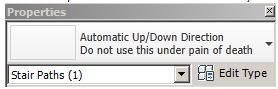
  • Automatic Up/Down Direction 


This will show an Up arrow and label on stairs going up from the current level, and a Down arrow for the top level of a stair;  the middle levels of multi-storey stairs show one up and one down arrow.  In many countries this type is never used, as it can cause confusion.  I have seen drawings where the text is lower case "up" and "dn";  rotate by 180 degrees and these are interchangeable - so if the drawing is read from the wrong direction the meaning of the letters is reversed (dangerous)!!


  • Fixed Up  Direction

This shows an Up arrow and label on all levels of a stair.  This is the standard method of annotating stair paths in many countries (including UK and Australia), but it may not be set as the default in the project template file.


Stair Path Properties

Each stair path has both instance and type properties, which will give you considerable control over how they appear on different views and at different scales.  Refer to Stair Paths at different scales for details on the individual properties.


Changing stair arrow types


  • When you create a stair it adds stair path arrow annotation to all relevant existing plan views that the stair shows in;
  • It will place the default path type for that project, which may be the Automatic Up/Down Direction Standard arrow (depending on how it was set in the original template, or if changed since then);
  • If this does not suit you, then you need to select the path arrow and change it to your preferred type (using the Type Selector);
  • BUT it will only change it on the view that you selected it on – all other views will still have the project default type (that includes views of other  levels of the same stair);
  • You could right-click and “Select all Instances in Project” and change them to the correct type, but this is not efficient as you’d need to do it every time you create a stair;
  • A better solution is to change the default:

Placing a Stair Path Arrow
If your stair does not have a path arrow in a particular view, then you need to place one:
  • From the Annotate tab select Stair Path (on the far right of the ribbon, grouped as a symbol, not a tag)
  • Check / change its type, eg “Fixed Up Direction” (from the Type Selector) before placing it;
  • Pick the stair

Setting the default stair path type
  • Place a stair (if you don’t already have one in the project);
  • Select the automatically generated stair path - if it is the correct one for your standards then you do not need to change the default.  However, if it is wrong, delete it;
  • From the Annotate Tab select new stair path, but be sure to change its type, eg “Fixed Up Direction” (from the Type Selector) before placing it;
  • From that point on, all newly placed stair paths in that project will be of that type, including automatically generated ones;
  • It would be wise to modify your standard project template, using this technique.  Don’t forget to  delete the stair from your template project before saving it.
  • NB. “Automatic Up/down” is a system family, so it cannot be deleted from a project.  You could always rename its type from “Standard” to “Do not use this type” in your project template file (or some such corporate standard threat).


Copying stair paths


  • When you create new views Revit does not add the stair paths in those views – there appears to be no way to force this;
  • Duplicate view does not copy stair path arrows (because they are annotation);
  • “Duplicate with Detailing” a view does copy stair path annotation, but of course it copies all the rest of the annotation too.
  • There is no middle way to duplicate a view and have it duplicate just the stair paths without any other annotation.  Theoretically you could Duplicate with Detailing, and then delete all the unwanted annotation from the view – but that is a workflow fraught with danger (not to be recommended, except for perfect users who have 100% understanding of the stair & annotation tools, and never have concentration lapses).
  • You cannot use “Tag all Untagged” for stair paths – although stair paths behave somewhat like tags, they are not actually tags.
  • You cannot copy and paste stair paths from one view to another (a bug);
  • You have to add stair paths to each stair in a new view one by one – it is the only way!

[Edit] How about we ask Autodesk to fix this (after 5 years)?  Please use these links to go to the Revit Ideas wishlist pages and vote up requests to fix these:
Moving Stair Paths


Stair paths are placed along the path line shown during editing a stair – usually along the centreline of the stair.  There are two ways to move them:


  • When you select a stair path, it shows two shape handle arrows.  These can be used to drag the paths off-centre.  If you drag it back, it will snap to the original path location.
  • If you require a path that is different from the simple one that is automatically generated – say you want to offset only one part of the arrow, you may need to “Convert to Sketch”  part of the stair, so that you could edit the location of the path line.  However, this is an operation that should not be undertaken unless you really have no choice, because once the stair components are converted, it is irreversible, and you would lose all the automatic functionality of the component.  In the example below, a complicated process is required just to offset one part of the path arrow – in this case it might be better to just create a manual stair arrow.   First the top run has to be converted, then the sketch has to be edited to move the run line, then the process needs to be repeated for the landing.   However, in this example, the landing and run might need to be sketch edited anyway, in order to get the supports to be correctly trimmed around the narrower part of the landing – this cannot be achieved using the shape handles on the landing.
 

  • Complex stair plans, such as 'T'-shapes will not create correct paths for both upper runs, so you will need to edit the landing sketch to get the path right

Mix ‘n’ Match Old and New Stair Annotation


In old stairs the path arrows and cut lines are an integral part of the stair, and their visibility and appearance can be somewhat controlled by instance and type properties.  New stair path arrows are purely annotation objects that can be placed per view.


The default settings for the new stair paths and cut lines make them look very similar to the old style ones (which could not be customised).  So you could have a mixture of old and new stairs in one project.  However, as soon as you start to change the look of either the new cut marks or stair path arrows then it will look very messy if you have a mixture of old and new stairs together.


Refer to Stair Paths at different scales for details on the individual properties.

Stair path arrows and View Types

Stair path arrows cannot be placed on Detail plan views


[Edit] How about we ask Autodesk to fix these two stair path arrow issues, since they have ignored my bug reports ?  Please use these links to go to the Revit Ideas wishlist pages and vote up requests to fix these: