BILT Speaker

BILT Speaker
RevitCat - Revit Consultant

Saturday, 14 September 2013

How to Indent a Revit Repeater on a Divided Surface

In a recent post by Andy Milburn over on Shades of Grey, he mentioned that it is not possible to indent the edges of a divided surface.  Well, that is absolutely true - Divided surfaces are unlike divided paths, which have an indent setting so that you can push the start or end nodes of the path in from ends of the underlying path.
Divided Path indent settings

The implication of this is that when you use a divided surface to generate a "Repeater" in Revit, the repeated adaptive components will overhang the edge of the divided surface.   In the example below, a one point adaptive component is placed on a node of the divided surface, then repeated - since the adaptive component consists of a cylindrical extrusion centred on the point, it is repeated to all nodes of the divided surface.


Since you cannot indent the edges of a divided surface, how can you prevent the repeater overhanging the divided surface?  If you made the extrusion offset from the adaptive placement point you could make it indent on one or two sides of the divided surface, but then it would overhang even more on the other sides.

However, in Revit there is usually a way to achieve what you want, so I attempted to find a way to indent the repeater, if not the nodes of a divided surface:

How to Indent a Repeater Pattern

You have to use some tricky thinking, and control where the repeater components will land - and prevent it from placing any part of the extrusion in the adaptive component on the edge nodes.
One way to do this would be to create a four point adaptive component:
  • First create a new adaptive component and place four points in a square arrangement
  • Make the points adaptive
  • Join the four points with four reference lines
Now you need to set out a centre point to host the geometry so that it remains centred whatever the arrangement of placement of points
  • Place four more points on the mid-point of each reference line (watch for the triangular snap symbol
  • Join those four points with two more reference lines
  • Place yet another point on one of the central lines
  • When you select the point, it will have an option (on the Option Bar, no less) to host it by intersection
  • Select that option, then pick the other central reference line
  • It will move the point to the central intersection.
  • NB. On reflection, you could skip the last four stages and just have one central linking reference line with a single point on its mid-point.  However, you could this intersection technique for other situations - perhaps if your extruded geometry needs to be more complex than a cylinder (see later on).
  • Select the central point and set its "Show Reference Planes" to "Always"
 

  • Set the active Work Plane to the horizontal reference plane of the central point
  • Place a reference circle centred on the point (assuming you want a cylinder)
  • Give its radius a parameter
  •  Select the circle and "Create Form"
  •  Select the top facet of the cylinder and give its Positive Offset a parameter called "Height"
  • Save and load the family into wherever your divided surface resides
  • Place one of the components onto four adjacent nodes of the divided surface in the same order that they are numbered in the family (its good practice to always use the same convention - say clockwise, unlike the diagrams shown here!!)
  • Select the adaptive component and click on the "Repeater" command (its the Array icons, but with the letter P on it)
  • If you snapped to the nodes correctly it should create a regular pattern
  • The extruded cylinders will be inset from the edge - however, they will only be inset by half the distance between nodes
  • If you want the cylinders to be inset by the full distance between nodes, you'll need to be more tricky:
  • Delete the repeater (you cannot dissolve it or alter its layout)
  • Place a new component on alternate nodes in a square pattern
  • The cylinder should then sit exactly over a node
  • Select the component and "Repeat" it
  • The pattern should spread over alternate nodes on the divided surface
  • The spacing will then most likely be too big
  • Select the divided surface and double the number of divisions (or half the spacing if it is set by distance)
  • Oops - we've now ended up with the same indent as before, so we may need to try another trick
  • The answer here is to coerce Revit into doing what you want by indenting the initial placement of the component 
  • Make sure that the first placement node you select is one node in from both edges
  • Select the component and repeat it
  • This will only work if the number of divisions is equal;  it will probably no longer work if you start playing around with number of divisions after repeating the component - so it pays to set the number of divisions correctly to start with.

If you want to be really clever, you could go back to the original four point adaptive component and give it some reporting parameters and use them to drive the cylinder size depending on the divided node spacing

Sunday, 1 September 2013

RTC Europe - Fractal Fun with Revit Repeaters and Adaptive Components

On 27th September 2013 I will be presenting at the Revit Technology Conference in Delft in the Netherlands.

The topic of my presentation will be:
"Fractal Fun with Revit Repeaters and Adaptive Components" - this will be a new, improved version of the presentations that I gave at RTC in Auckland and Vancouver earlier this year.  Yes, RTC is so good that I'll be attending at all three venues this year.


As part of the presentation, all being well, I intend to give a live demonstration of how to build a fully parametric Revit model of the roof structure shown below - within about 30 minutes.  This is the Gare do Oriente in lisbon, designed by Santiago Calatrava.

Based on feedback I received from RTC in Vancouver, I have updated the handouts to reflect changes made to the modeling process that I will demonstrate.  For anyone who downloaded my presentation from the earlier RTC events, you might like to get an udated version from RTC Europe.

Gare do Oriente, Lisbon by Santiago Calatrava

Every single Revit Technology Conference has been really fantastic, and I have learned new things every time - usually they have saved me more time than the hours I spent there.  I have been able to go back to the office and quickly solve problems that have had me stumped before, or implement new techniques.

Wednesday, 14 August 2013

Mona Lisa's Eyes Follow the Revit Camera Wherever it Goes

Using Adaptive Components to make Mona Lisa's whole face follow you around the room


Have you ever wanted to make all your 2.5d trees or people face the camera in a perspective view in Revit?  No?  Well I'm going to tell you how anyway - maybe it will help someone come up with new ideas of how to use this technique.

  • First create a new "Generic Adaptive Model" family;
  • Place two points along the X axis;
  • Select the points and make them adaptive;
  • Join the points with a reference line;

  • Set the workplane to be the vertical plane of the adaptive point (1) at the start of the reference lin, perpendicular to the line;

  • Alternatively you can pick the end workplane of the reference line itself;
  • Use model (or reference) lines to trace the 2d outline of a person;
  • Select the lines and create a form - an extrusion of the person outline;
 
  •  Select adaptive point 2, move it around to flex the family;
  • The person extrusion should remain perpendicular to the line, and it should rotate around to follow it (providing it was correctly associated with the work plane of point 1;
 

  • Return the adaptive points to the x axis location;
  • Add some model line detail (or more extrusions as desired), making sure that they are either hosted on the same workplane or on the form itself - in this case I have added a Mona Lisa face to make it more fun;
  • Flex the family again by moving adaptive point 2, to check that all geometry is correctly associated - in this case the face rotates but Mona Lisa's eyes will keep looking at you;

  • Now the Mona Lisa family is ready to use;
  • Load her into a project;
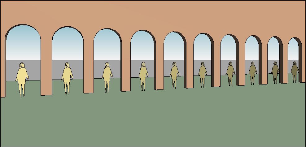
  • In this example I have created a series of arch doorways;
  • I have also created an object to represent the camera location - it can be any object, but the best thing would be to create a "camera family"


  • Place a Mona Lisa adaptive family - first point in the middle of an archway, second point snapping onto the camera object (important, it must snap to it)


  • Place a second Mona Lisa in the second archway, but snap its second point to the same camera object;
  • Place as many more Mona Lisas as you need, each sharing the same second point on the camera object;


  • Note how each Mona Lisa is slightly rotated, so that they are all looking at the camera object;
  • Now create a camera view, ensuring that the camera location is approximately the same as the camera object;
  • All the Mona Lisas will be facing the camera;
  • You might argue that her eyes would have been looking at the camera without rotating the whole body - true, but this technique will work for anyone other than Mona Lisa;  or for a tree or any other 2.5d (flat extrusion) entourage family;


  • Create another camera view from a completely different angle;
  • The Mona Lisas will no longer be facing the camera in this view


  • Check this out in plan view too - they are all still facing the first camera location;
  • Right-click on the second perspective view in the Project Browser, and select "Show Camera" to see where it is in plan;
  • Place a marker - eg a cross in plan;
  • Move the camera object to the new camera location;
  • All the Mona Lisas should rotate together to face the new camera position

This may seem like a clunky workflow, but once it is set up all it requires is a single move of the camera object to each view location - so its not going to work if you have several views on one sheet.

Of course all the people don't have to look the same - they just need two adaptive points to work.  Each person could have a parameter for a small rotational adjustment within the family to give some variation - each one could face slightly away from the camera, but close enough not to get any side on views of extrusions.  This would ensure that the scene does not look quite so artificial.

There is an alternative method of placing the people - more on that next time.

I hope this helps someone out, or inspires some new method of improving presentation methods in Revit . . . .


Thursday, 1 August 2013

Scaling Revit Families Nested in Curtain Panel Patterns

Credits First

This post would not have happened without discussions at RTC or blog posts by the following people:
What I am showing here is a development of all those ideas, combined with a concept that I came up with for my RTC presentation "Fractal Fun with Revit Repeaters" earlier this year - more on that at a later date.

How to trim the edges of a pattern of repeated scaleable Revit families

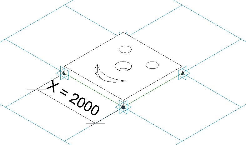
The image on the left above shows a repeated pattern of complex shapes within a regular rectangular boundary - relatively easy to achieve in Revit!  On the right the boundary has been trimmed, and the pattern gets trimmed with it - not so easy.
Add in the ability to scale the pattern elements and it gets a whole lot trickier. 

Kelvin Tam showed us how to nest a planting category family into another planting family and then nest again into a different category family - this allows us to use the ability of planting category to automatically scale any irregular shape without having to create complex formulas and controlling geometry (see link above).

David Light applied that technique to nesting planting categories into curtain wall panels to create arrays of scaleable science fiction monsters marching across the landscape.

Andy Milburn applied the same technique to creating Musharabiya screens out of curtain walls.  He noted that there was a limitation of not being able to trim the edges of the pattern because curtain wall panels won't be be cut.

To solve that problem I used Marcello Sgambelluri's technique of questioning which similar category or situation does Revit allow you to do what you want?  In this case I knew from my RTC presentation "Fractal Fun" research that Revit will cut the edges of curtain wall panel pattern families when applied to divided surfaces.  So we should be able to apply that principle here - the only limitation being that it must be done in the conceptual modelling or adaptive component environment.

Here is how to do it:
  • First start a new planting category family and create the desired pattern element within it - in this case a simple smiling face within a square (but it could be a complex geometric design).
  • Then start another new planting category family;
  • Load the first family into the second;  this is to make use of Revit's capability of automatically scaling plants and trees - it only works with nested families;
  • Start a new "Curtain Panel Pattern Based" family;
  • Place a dimension between two adjacent points; 
  • Make the dimension an instance reporting parameter 


  • Load the second planting family into it, and place it on the pattern.  You may need to devise a way to control the location of the component by hosting it on specific points
  • Select the planting family and link its "Height" parameter to the new reporting parameter in the pattern family;  you may need to add a formula to scale it up or down to match the size of the pattern grid (depending on the original family size) 
 

  • Create a new mass family or In-Place mass within a project;
  • create an irregular shaped form (can be a flat surface or an extruded shape);
  • Select a surface and divide it
  • Make sure the divided surface pattern is square and orthogonal - you may need to rotate the grid or set the spacing to fixed distance;
 
  • Load the curtain panel pattern family into the mass
  • Select the divided surface and change its type to the pattern family - it should automatically trim the pattern elements around the edges
  • NB. I think this did not work in the first version of the new conceptual massing in v2010?  but it seems to have been changed at some point since.
 
  • Depending on the grid spacing and location, Revit sometimes misses out small pieces or fails to trim elements that are hanging over the edge by only a small amount.

  • Occasionally it gets it quite wrong - in this example it was an in-place mass, which looked ok until the mass was "finished".


All this was done without tricky formulas - just by using the tools that Revit developers gave us, albeit not in ways that they expected us to use them.  There are obvious limitations of not being able to apply this to a normal curtain wall, so you have to use the massing tools to create a divided surface.

Obviously you aren't going to make smiley face patterns, but you should be able to apply these principles to real architectural design solutions.

Sunday, 28 July 2013

Revit Scaleable Spline Tree Family

Having returned from RTC in Vancouver a couple of weeks ago, I decided to put into practice some of the things that I learnt at the conference.  It was another great Revit conference in a fabulous location - Vancouver is a beautiful city, and the waterfront has been really well designed and carried out.  Aside from catching up with friends, I met lots of interesting people and attended plenty of good classes.  Although I attended Marcello Sgambelluri's class on scaling families at RTC in Auckland, it was also a big talking point in Vancouver.  I asked several people if they had attended the class, and many enthusiastic people had;  some others said that they did not want to see how to scale a Revit cow or elephant - well they missed out on a treat, because we learned many tricks that could be applied to totally different areas of Revit. 

Here is one idea that I have developed based on one of the methods that Marcello used to scale classical column families:
Marcello Sgambelluri - Scaling Classical Order of Columns

Scale By Spline

This concept has also been explored by others, notably
Andy Milburn - Spline Sailing

but I first need to describe the concept here. 

A spline can be scaled just by dragging one of its end points.  To control this within a scaleable Revit family, you need to lock or attach the end points of the spline to something that you can dimension.  Although you can dimension the end points directly, it is better to use something like a reference plane.  Here is a simple rig to demonstrate this process:
The vertical reference planes and width parameter will be used to control the distance between start and end of the spline, and in turn its scale.
The offset reference plane and parameter are required in order to control the location of the spline.
Once the rig is set up, draw a spline between the two top reference plane intersections

Use the align tool to lock the ends to the reference planes, in both directions (4 locks required)

Change the width parameter to check that the spline is locked to the vertical reference planes and that it scales properly.
Change the Offset parameter to check that the spline is locked to the horizontal reference plane.

This example establishes the principle of being able to control scaling and location of splines using reference planes.  The spline end points do not need to be orthogonal to each other - they can also be at an angle.

Revit Scaleable Spline Tree Family

We can now apply this principle to multiple splines linked to each other, to create a simple tree family.  This example is proof of concept, and is only done in 2D, but it could be applied to 3D trees.

First make a rig of reference planes that are controlled by parameters
Then draw a series of splines between each reference plane intersection.
Lock the ends of the splines to the intersections using the Align tool (and then padlock)
Try flexing the overall height parameter - this will not only change the overall height, but it will not affect the other parameters.  So only parts of the tree will scale, and others will not be affected depending on how the parameters are arranged.  In this example, the tree trunk is not affected by the change in height - only the top part of the tree scales.
Changing the intermediate parameters will alter the overall shape as well as the width
 Different tree forms can be achieved by playing around with the parameters
One tree family can be used to create multiple tree types that vary in shape and height
By adding a few more reference planes and splines it should be possible to create a family that has independant tree height and spread parameters.  And all this can be done without having to nest one planting family inside another - it works without nesting.

No doubt there will be people who say that this is not practicable, or that the trees look terrible - but this is only a proof of concept.  I'm hoping that it will give more ideas to others who can run with the concept and create wonderful flexible tree families.