BILT Speaker

BILT Speaker
RevitCat - Revit Consultant
Showing posts with label tile. Show all posts

Sunday, 17 February 2019

Stretcher Bond Hatching in Revit

A few years back I posted a description of how to create a complex custom hatch pattern for Revit - that example was for repeating octagons.  Since then I have often needed to quickly create much simpler patterns such as stretcher bond elevation views for bricks, blocks and tiles.  The Octagon pattern was quite complex and it still takes a while to get your head around the logic - so here is a much easier to follow set of examples:


Pattern Definition Format

The pattern file is a text file, saved with a '.pat' extension.
Definition of units (important for metric):
;%UNITS=MM

Each pattern definition has an * prefixed header :   a title and description separated by a comma
      *Stretcher 400x200,   400mm x 200mm stretcher bond
Drafting or Model definition:
       ;%TYPE=MODEL
Each line repeat (in the pattern) is described in one row of text, with comma delimited format.  eg:
0,     1200, 1000,         0,  1000,       400,  -1500

  • Angle  = angle of line from horizontal measured in an anti-clockwise direction
  • Origin x = horizontal distance of start of line from setout point (always orthogonal)
  • Origin y = vertical distance of start of line from setout point (always orthogonal)
  • Shift u (x axis of line) = offset distance of start of repeat line measured parallel to start of line
    (in the direction of the line,  ie. to match the angle).  The Shift values are measured from the start of the line, not from the setout point.
  • Shift v (y axis of line) = offset distance of start of repeat line measured perpendicular to start of line
  • Pen down = length of solid line measured in the direction of the line (optional - it draws a continuous line if omitted)
  • Pen up = length of gap in the line before the next segment of the line starts repeating (measured in the direction of the line);  is always a minus value.  (optional - as per pen down)
NB. I have labelled the shift directions as u & v (not x & y, as Autodesk labels them) because the directions relate to the axis of the line, not the whole pattern - so a vertical line would have a u offset measured vertically (labelled as x direction by Autodesk, which is confusing).

Stretcher Bond Hatching Definitions


A typical staggered tile pattern (stretcher bond) consists of :
  • a series of continuous horizontal lines at regular spacing;
  • Short vertical lines that run between alternate horizontal lines, at a spacing equal to the length of the brick/block/tile
  • Another set of short vertical lines that run between alternate horizontal lines, at a spacing equal to the length of the brick/block/tile - but these are typically offset horizontally by half a length and vertically by one pattern height.
These should almost always be defined as MODEL patterns, as they are meant to be dimensionally correct on the surface of the material.

There are actually two ways to define this:

Option 1 - separate definitions for the two vertical lines

*Stretcher-450x150-1/2,      450 x 150 1/2 stretcher bond
;%TYPE=MODEL
0,         0,0,           0,150
90,       0,0,           0,450,        150,-150
90,    225,150,      0,450,        150,-150

The first row defines the horizontal lines
0,         0,0,           0,150
  • The lines are at zero degrees (horizontal)
  • The first line starts at 0 offset from the origin, both x and y (0,0)
  •  The repeat has a shift of zero horizontally (x or u), and 150mm vertically (y or v) from the line origin (0,150),
  • The next repeat is the same values (0,150) from the start of the previous repeat. 
  • The line is continuous, as the are no pen up/down values


The second row defines the first set of vertical lines
90,       0,0,           0,450,        150,-150
  • The lines are at 90 degrees (vertical )
  • The first line starts at 0 offset from the origin, both x and y (0,0)
  •  The repeat has a shift of zero vertically (u) , and 450mm horizontally (v) , from the line origin (0,450)
  • The next repeat is the same values (0,450) from the start of the previous repeat. 
  • The line is segmented, 150mm solid, 150mm gap (pen up/down 150,-150)
The v shift in this instance is horizontal, perpendicular to the line, with a positive value to the left of the line origin (same as pattern setout point in this case). 
  • As the pattern is symmetrical, it makes no difference if the v shift value is positive or negative
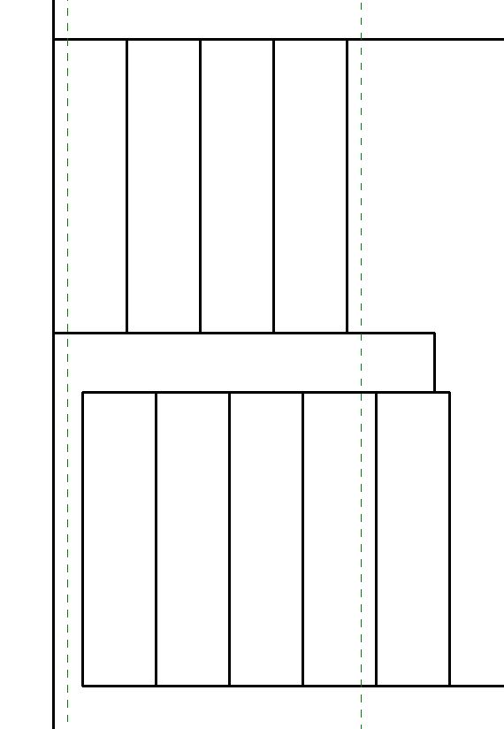
  • Seen below in context, the pattern repeats in both directions from the origin:


The third row defines the second set of vertical lines
90,    225,150,      0,450,        150,-150
  • The lines are at 90 degrees (vertical )
  • The first line starts at 225mm x offset from the origin, and 150mm y offset from the origin (225,150) - ie. half a tile along and one tile up.
  • The repeat has a shift of zero vertically (u) , and 450mm horizontally (v) , from the line origin (0,450)
  • The next repeat is the same values (0,450) from the start of the previous repeat. 
  • The line is segmented, 150mm solid, 150mm gap (pen up/down 150,-150)


Option 2 - one definition for both vertical lines

*Stretcher-450x150-1/2,      450 x 150 1/2 stretcher bond
;%TYPE=MODEL
0,         0,0,           0,150
90,       0,0,       150,225,        150,-150


The first row defines the horizontal lines as per previous method
0,         0,0,           0,150

The second row defines the vertical lines
90,       0,0,       150,225,        150,-150
  • The lines are at 90 degrees (vertical )
  • The first line starts at 0 offset from the origin, both x and y (0,0)
  •  The repeat has a shift of 150mm vertically (u) , and 225mm horizontally (v) , from the line origin (150,225)
  • The next repeat is the same values (150,225) from the start of the previous repeat. 
  • The line is segmented, 150mm solid, 150mm gap (pen up/down 150,-150)


  • As the pattern is symmetrical, it makes no difference if the u and v shift values are positive or negative
  • Seen below in context, the pattern repeats in both directions from the origin:


One Third Shift Patterns

The same principles can be applied when the bond is staggered by differing proportions.


Option 1 - separate definitions for each vertical line


*Stretcher-450x150-1/3,   450 x 150 1/3 stretcher bond
;%TYPE=MODEL
0,          0,0,         0,150
90,        0,0,         0,450,       150,-300 
90,    150,150,     0,450,       150,-300
90,    300,300,     0,450,       150,-300


 90,    150,150,     0,450,       150,-300

  • 90 degrees
  • 150mm x line origin, 150mm y line origin
  • Zero u shift repeat, 450mm v shift repeat
  • 150mm Pen Down, 300mm gap (Pen Up)


 90,    300,300,     0,450,       150,-300
  • 90 degrees
  • 300mm x line origin, 300mm y line origin
  • Zero u shift repeat, 450mm v shift repeat
  • 150mm Pen Down, 300mm gap (Pen Up)

Option 2 - one definitions for all vertical lines

*Stretcher-450x150-1/2,      450 x 150 1/2 stretcher bond
;%TYPE=MODEL
0,         0,0,           0,150
90,       0,0,       150,300,        150,-300
Horizontal shift (v) repeat has to be 2/3 of a tile (300mm)

As the joint offset is not half a tile, the same result can be achieved with a negative v shift repeat of -150mm:
0,         0,0,           0,150
90,       0,0,       150,-150,        150,-300


An offset by one third to the left could be achieved by a positive 150mm v shift:
0,         0,0,           0,150
90,       0,0,       150,150,        150,-300


Two Third Shift Patterns

Some patterns cannot have their vertical lines defined by only one row, as you can't define a consistent diagonal repeat.  Therefore you must have multiple rows for the vertical lines.

*Staggered-450x150-2/3, 450 x 150 2/3 stretcher bond
;%TYPE=MODEL
0,          0,0,        0,150
90,        0,0,        0,450,     150,-150
90,    300,150,    0,450,     150,-150


The direction of stagger can be changed with the x origin value:

*Staggered-450x150+2/3, 450 x 150 2/3 stretcher bond
;%TYPE=MODEL
0,          0,0,        0,150
90,        0,0,        0,450,     150,-150
90,    150,150,    0,450,     150,-150

Flemish Bond

More complex brick patterns require extra rows of definition:


*Flemish-240x86,     240 x 86 (Australian Brick size) Flemish stretcher bond
;%TYPE=MODEL
0,           0,0,         0,86
90,         0,0,         0,360,       86,-86 
90,      240,0,        0,360,       86,-86
90,        60,86,      0,360,       86,-86
90,      180,86,      0,360,       86,-86


You could continue this theme with increasing random looking patterns, but I'll leave that for you to figure out . . . . . .


Friday, 23 October 2015

Weird Stair Stuff - part 6 - Showing Concrete Stairs Under Tread Finishes

I was recently asked if it was possible to show a concrete setout plans (and sections) for a monolithic Revit stair that has a tiled finish or timber treads on top of the concrete - ie. to hide the finish and show the concrete riser lines only (which are in a different plan location to the finishes risers shown on the architectural plan).  You would think it should be an easy task given that most structural engineers would want to see only the concrete part of a stair.  Wrong!

By default, in an architectural plan view, Revit displays the finished nosing lines and the hidden riser lines (which may be coincident in plan if you do not have a projecting nosing).  One of the reasons for this is that Revit is not displaying the 3D model in plan views - it displays a hybrid 2.5D version that represents the stair in plan according to Revit's mysterious rules and system controlled subcategories (which are quite frankly, very limiting).
Normal architectural plan view of stair
Changing the Discipline of the view to structural, makes no difference to stairs.  Hiding various stair subcategories will not show the hidden concrete underneath, whatever you try.  If you hover the mouse over the run (and tab to get just a run), it highlights the actual 3D model with all the hidden lines available - but they disappear as soon as you select it - how tantalising!
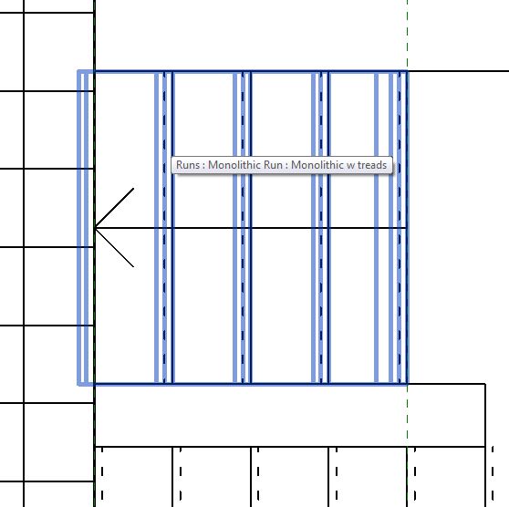
Pre-select run shows hidden lines of concrete below

If you hide the floor finish at the top of the stair (in this example it is modelled as a separate floor) you can see that there appears to be a gap - this is because Revit stops drawing the plan where it expects the top nosing line to be rather than where the top riser is (even though it does not model the nosing if your stair 'Ends with Riser').
Gap at top of stairs when floor finish is hidden

Back in the section view, if you turn off the 'Treads/Risers' subcategory it leaves just the concrete substructure.

Notice that the concrete actually extends to the back of the riser in section (and 3D) but this is not shown in plan.  The section also has a couple of other issues:
  • The concrete at the top of the stair stops in line with the back of the top riser, where in fact it should extend up until it meets the underside of the floor slab.  Obviously the stair has no knowledge of where that slab is or how thick it is, but there should be a way to deal with this.  There is a Run property for 'Extend Below Slab' so why not have one at the top.
  • There appears to be a joint between the landing and the upper run even though they are the same material - in fact it is a step in the landing because the concrete landing edge aligns with the nosing rather than the concrete riser.  This would need to be manually adjusted if you want them to align or if you want a finish applied to the landing edge.
Concrete Section - treads/Risers hidden
This is getting close to what a structural engineer might want to see, or for an architectural concrete setout drawing.  So how do we get this to display the same information in plan, when Revit really does not want to do so?

As a workaround, we could try using one of Revit's really weird features, as described in my post about stair arrows and detail views:

Detail view callout

Create a detail view callout of the stair.

This type of view (Detail plan view) is actually a true 3D view (a horizontal section), which does not use the normal Revit 2.5D representation of stairs (and ramps).  The stair shows the top riser line (including thickness) and the actual nosing locations where modelled.  In the snapshot below the floor finish is hidden so you can see the top riser.
Stair in Detail plan view type

So now it follows the subcategory rules that normally apply to a section:
  • Nosing Lines, Riser Lines and Outlines are not relevant to this view type
  • Treads/Risers subcategory does apply - try changing the colour override to test it
Treads and risers overridden in detail plan view

Now try turning off the visibility of the Treads/Risers subcategory - and magically you can see the concrete underneath, because that is controlled by the overall 'Stair' category.

Of course there are some downsides to this method of creating concrete setout plans - Detail plan views are not normal Revit views:
  • You cannot place stair path arrows on detail views (although you can place stair numbers)
  • You cannot 'Reference Other View' callouts to regular plan views - so you would have to work out your view referencing carefully.
  • Detail views do not have a 'View Range', so you have to rely on the parent view or 'Far Clipping'
  • View cut plane is controlled by parent view - and cannot be overridden
  • You cannot use Plan Regions
  • If someone deletes your parent plan view, Vamoose detail view.
  • the list goes on . . . . .


Refer to  True 3D RCP View of a Stair in Revit for more uses of this technique
Refer to stair arrows and detail views for more detail on the downsides of this technique
Go to Revit Stair & Railings Index Page