
 |
| Loch Ness monster created in Revit |
In a recent blog post I was trying to create a swept blend (or loft) along a single spline path
and I encountered a few problems, which were mostly (but not all) solved by including the spline path as part of 'Create Form' process. That was just a preliminary test for what I ultimately wanted to create: A swept blend along a sinuous multi-segment path made up of arcs and lines - not a spline (as seen above).
Here follows the next instalment in my trials and tribulations. I will start simply by comparing the traditional methods and conceptual massing creation of a sweep, before moving on to a swept blend.
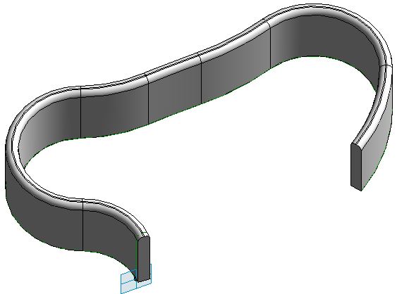
Traditional Sweep
In the traditional family editor, Revit can easily create a sweep along a sinuous multi-segment path, unless the radius of a curve on the path is too small and causes impossible geometry. This example below is a simple sweep of one profile along several linked arcs and lines. It creates a pretty good looking form if the arcs/lines are at perfect tangents to each other (in both the path and profile) - it does not show any join lines. |
| Traditional family editor sweep |
CME Sweep
Try creating it in the Adaptive/Conceptual Massing Environment (CME) and you don't get such a good result - and there is less likelihood of Revit actually creating the form at all. The example below is created using the same geometry as the one above, with some provisos:- The sweep path of perfect tangent lines and arcs had to be traced as reference lines with the pick line tool as you cannot copy sketch lines from the traditional family editor into the Adaptive/Massing environment (Grrrr - why not?).
- The profile had to be recreated as an adaptive component profile as you cannot use regular Revit profiles in CME. Refer to Swept blend using profiles in Adaptive Components for how to create and host the profiles.
 |
| CME Sweep using one profile and reference lines/arcs as path |
CME Swept Blend
If you try something similar as a swept blend you run into roadblocks very quickly:- Host another profile (similar or in this case same shape, lower height) at the other end of the path
- In this example the easiest way to do that is to place a point on the reference line/arc; then host the adaptive profile onto the point

- Select the two profiles and the chain of lines
- Create Form
- Computer says 'No'. Refer to Unable to Create Form for more variations on this dialog box
 |
| CME Swept blend on multiple arc/line path - failure |
- If you try moving the host points further around the arcs on the path so that the path is less sinuous it still fails

- Try putting the host points and profiles on almost straight section but hosted on different lines - still no go
 |
| Another swept blend failure |
- It is not until you put the two profiles onto the same line or arc segment that it actually succeeds in creating a form (if you select only that segment and two profiles)

Another approach is required:
How to convert the arcs and lines into one path? Well you could try tracing a spline over the top - but that has several problems:
- A spline is not easy to set out on a drawing for construction; it cannot be dimensioned
- A spline will not follow the original path accurately - it will bulge out when there should be a smooth transition from arc to straight line
- The spline will not update if the reference line path is changed
Divide Path
Another option is to use an inbuilt Revit technique: 'Divide Path' - this creates a single element that sits on top of multiple lines/arcs selected in a chain.

If you select only some of the profiles, and create a form, you can see that it will not follow the path at all closely, especially if they are not close together.

If you create separate forms for each pair (or trio) of profiles you get pretty awful results:

So, is the answer to increase the number of nodes on the divided path and add more profiles?
It gets a bit tedious placing adaptive profiles, and sometimes they flip for no apparent reason.
So maybe we can use another Revit tool to place multiple profiles: Repeaters
Repeaters
If you place just one profile on a divided path node, you can use the 'Repeat' command to array the profile onto every node (they still sometime flip!).If you select all the profiles, Revit should have a better chance of more closely following the path as it joins them all, right?
The next problem is that you cannot create forms directly from a repeater - you have to first dissolve the repeater using the new (in v2015 r2) 'Remove Repeater' command.


 |
| Unable to create Form |


That is an issue to be solved in the next post Part 2 - sadly it is not as simple as you might guess (if you have followed the process so far)
No comments:
Post a Comment