BILT Speaker

BILT Speaker
RevitCat - Revit Consultant
Showing posts with label subcategory. Show all posts

Sunday, 17 March 2019

Glazed Doors in Window and Door Schedules in Revit

I started out writing this blog post about the behaviour of subcategories in nested families.  On closer investigation, the weird behaviour I intended documenting was not as I had thought - still a bit strange but not quite worthy of a post all to itself.  So I have changed tack and turned it into a discussion about how to get a glazed door family to appear in both door and window schedules.  Many experienced Revit users should already know this, but for those who do not, read on.

Schedules and Categories

Typically door and window schedules are created separately as single category schedules. Multi-category schedules have too many limitations to make them work efficiently for this task. A door or a window is usually either one of those categories, and therefore it can only appear in one of the schedules.  What if you have a window assembly that contains a glazed door? or a sliding glass door, which you want to show in the window schedule (because it is glazing), but also in the door schedule (because it hosts door hardware)?  This common requirement seems problematic in Revit, but there is a way around it . . .

Workaround:

Shared Nested Family

When a nested family is 'Shared', it behaves differently to the parent family in terms of subcategories.
For example, you might have a window parent family, that contains just a frame (or a fixed glass side panel).  Inside this could be a nested sliding door family.  Providing the door family is set to 'Shared', then it can have its subcategories independently controlled (by View Visibility) in the project;  it can also be individually selected, tagged and scheduled (as a door); the parent family can be tagged and scheduled as a window.

Nested Door Family Category Settings

Nested Door Family Subcategory

Parent Window Family

Parent Family Category

Parent Family Subcategories

Nested Door Family in Parent Family

Tagging and Schedules

Standard door and window families are normally tagged separately according to category
Once placed in a project, the combined door/window family can be tagged for either category:


Tag the whole family for the window category tag

Tab select the nested door family to tag it

Scheduling

  • The combined window/door family will appear in a window schedule. 
  • The Nested door family will appear in a door schedule

Category Visibility

This example shows a single swing door nested family in a window family (with fixed window panels either side).  In the project, both door and window categories/subcategories affect the sub-element display:
All Categories On

Door Panel Subcategory Off

Window Category Off - Door Category On

Non-shared Nested Family Categories

When a normal 'non-shared' family of one category is nested inside another family of a different category, it behaves as if it is part of the parent family in terms of categories.
Unshared Family Settings
In the parent family (in Family Editor), the nested family still shows its category when selected
Non-Shared Nested Door Family in Window Parent Family
When loaded into a project the whole window can be selected, but not the nested door family. 

Window family with non-shared nested door - in project

Changing the visibility of the Door category does not affect the nested door.
Door Category Off, Window Category Visible

Hiding the Window category, (while the door category is visible) hides the whole family, including the nested door
Door Category Visible, Window Category Off

This behaviour is as expected.

Weird Revit Behaviour:

Non-Shared Nested Families

However, if the nested families have elements of a specific subcategory (of the Nested family category - door) the element's visibility is still controlled by that nested family subcategory.  This does not really make sense if the nested family is not shared.
Door Panel Subcategory Off


This can be very confusing, as you have no way of knowing what category the nested family is, without editing the parent family.  As far as the user is concerned, the family is a window - since you cannot select the nested door in the project, the user will not be aware that it even has a nested family, let alone that a subcategory that has nothing to do with windows will still affect it.


Saturday, 26 January 2019

How Do You Solve a Problem Like Ma Railings?


Have you ever encountered a problem with out-of-control railings in Revit?  OK, so maybe the structure shown above is not a haywire railing, and was meant to be like that, but most Revit users have struggled with trying to model railings as they should be.

How Do You Solve a Problem Like Ma Railings (in Revit)?  *


* with apologies to Richard Rodgers for misappropriating his song title (How Do You Solve a Problem Like Maria? from the Sound of Music, By Rodgers and Hammerstein) - not to be confused with Richard Rogers (no d), the architect who designed many famous buildings, such as the Pompidou Centre in Paris (with Renzo Piano) and the Lloyds Building in London.

Richard Rogers surely did not struggle with trying to model railings in Revit, as those buildings were designed long before the advent of such software.  These days we certainly do struggle with the software - Revit has been around for almost 20 years and it still it does not enable us to model Railings the way we want them (except for the most simple handrail).  There are many problems with the railing tool in Revit, some of which have been documented on this blog - see the list below.  Over the years, we have benefitted from several minor improvements to the railing tool - for which we are very grateful.  However, there is one fundamental problem that has not been resolved - and that is the inability to control the location of individual balusters.

Baluster Placement - a Fundamental Flaw

The railing sample file shows some relatively complex looking examples - but these are just straight runs on the level.  As soon as you try to use them on stairs, things start going wrong with the baluster placement.

This example is done using two alternating balusters - one is just a post, while the other is glass with fixings.  The glass baluster is very good at adjusting the angle of its top and base (if you create the family properly). 
 
When it comes to spacing, it is pretty hopeless:  you get gaps whenever there is a break in the pattern.
Standard railing with glass balusters
There are some limited controls within the baluster placement type properties, but no single combination of settings will ever work on the whole stair railing.

Spreading the pattern to fit does resolve some issues, sometimes. . . .

Changing the 'Break-Pattern' property to 'Never' can have some weird results

Reverting the pattern to 'Centred' does not fix it either - you may end up with panels across a change in angle, where the panel is not trimmed properly.

Workarounds

There are a number of ways that people get around these problems, but none of them is satisfactory:

1.  You can try using 'Handrail Supports' to represent balusters, but that has at least two problems:
  • Handrail supports do not respond to changes in angle of the stair, so you need to build that in as a user control that has to be manually set every time
  • Handrail supports can be unpinned and then moved (or changed to another type), but the moving process is very tricky - see Moving Handrail Supports
    It is also possible to very easily lose the positions by accidentally resetting the railing.
2.  Model the glass as a continuous rail element, use balusters and/or handrail supports to represent the fixings and vertical joints in the glass.  More on that another time.

3.  Model the railing 'in-place'.  This is a really bad idea as it screws up the subcategories, visibility etc;  And worse still, it does not update when the stair changes

4.  Just model a Top Rail / Handrail (with no balusters), which shows up in plan.  Document the railing in 2D as drafting views or as detail elements on stair sections.  This is a terrible solution (very un-Revit-like), but it can save huge amounts of modelling time - so it is done quite commonly in the industry.  Of course, it can lead to errors on site . . . .

Railing Fixes

If we had the ability to control the baluster placement in much the same way that curtain walls operate, it would help resolve this fundamental flaw in the railing tool;  this would require the ability to include variable width panels too.  Of course there need to be many other minor fixes in addition to that. 

On the Autodesk Revit Roadmap, Railings were flagged as 'fixed', a couple of years ago, on the basis of a number of minor enhancements.  Clearly it is nowhere near being fixed - see this request on 'Revit Ideas'  Railing Overhaul - Resolution of Limitations - from Chris Price (Mr Spot).

Weird Railing Stuff Blogs

Over the last few years I have posted many blog articles on the many weird quirks of using Revit to model Railings.  Some articles just document the inconsistencies and strange behaviour - just so you know what is going on; other articles offer some workarounds and ground-rules that might help you along:

Revit Railing Enhancement Requests

Autodesk  have a 'Revit Ideas' website that allows you to vote for enhancement requests.  I have compiled a list of stair/railing related ideas - please, all of you vote for some of these requests - if you don't vote, Autodesk will continue to consider them as fixed.

Friday, 1 April 2016

Revit Stair Subcategories and Materials

Last year I posted a detailed description of what the 'new' stair component subcategories do in different views - plan vs section.
It seems that I missed something - Dan Stine (author of several Revit text books) has pointed out that the Treads/Risers subcategory does actually have an effect in plan views:
It controls the materials and surface patterns of the treads.  I did some testing to understand the subtleties of how this works. . . . .

Here I am using my subcategory visibility colour overrides to make it easier to see what is being controlled by which subcategory.

 Normally turning the 'Treads/Risers' subcategory seems to have no effect in a plan view.
This would be the case for one of two reasons:
  • If your monolithic stair run does not have a separate tread
 
  • If the stair run does have a tread, but the tread material does not have any surface pattern
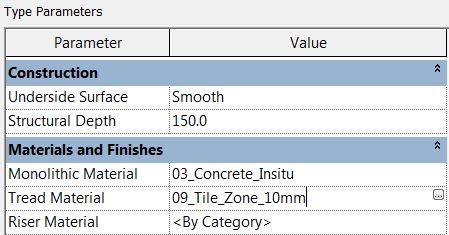
Tread material - Run type property
 
Material properties of stair run tread

However, if the material of the tread is changed so that it has a surface pattern, this will display in a plan view

It looks different depending on the visual style of the view:
Hidden Line View with tiles on treads
Shaded View with tiles on treads
Realistic View with tiles on treads

If you then hide the Treads/Risers subcategory, the tread material will no longer be displayed.  Instead it will display the material of the underlying stair structure - if it is monolithic, that would most likely be concrete.

We normally do not have a surface pattern on concrete because it would show up in too many views.  However, if you do have a surface pattern, it will show once you have hidden the treads


Hidden Line - concrete surface pattern
Shaded View - concrete surface pattern
Realistic View - monolithic concrete stair


Really Weird Stair Stuff

In order to hide the surface pattern of the underlying monolithic material in a plan view, you have to turn off both 'Nosing Line' & 'Riser Lines' subcategories.  Turn off just one or other of them and you hide the lines, but not the material surface pattern.  That makes no sense to me.
Plan subcategories for materials


 How do you hide the material of the underlying monolithic structure?
  1. Make sure the material does not have a surface pattern, and view it in Hidden Line or Shaded View.  Or:
  2. Turn off the 'Nosing Line' and 'Riser Lines' subcategories.  That could be frustrating if you need to see the nosing or riser lines themselves!  
    Or (the better solution):
  3. Go to the Surface Pattern override for the whole stair;  untick the Pattern Overrides 'Visible' checkbox (won't work in a realistic view)
        The Pattern will then list as 'Hidden'


Which one of the three solutions you choose depends on exactly the result you are after, and on what Visual Style setting you have for the view.

For a Realistic View, you can hide the tread material (by Tread/Riser subcategory) but cannot hide the underlying monolithic material at all.

Material Linestyle Overrides 

Unlike the actual linework of the stairs, the lines within the surface patterns cannot have their weight or linestyle overridden in the Visibility Graphics dialog - they follow the standard rules for hatching lines.  The colour can be overridden, but you have to change the overall stair category pattern colour override, not the subcategory line colour override.  This means that the button to click on for colour override is quite different to the location of the 'Treads/Risers' subcategory visibility control checkbox(es).


The actual hatching pattern can be overridden from the same dialog - this allows you to choose a totally different pattern just for that view.  If you set it to "No Pattern", it just clears the override, rather than temporarily removing the pattern as an override - which is frustrating if that was the result that you wanted, particularly if you just tried to override one element, not all in that view.

The line weight of the surface patterns cannot be overridden by view, but that is another story . . . .

Friday, 23 October 2015

Weird Stair Stuff - part 6 - Showing Concrete Stairs Under Tread Finishes

I was recently asked if it was possible to show a concrete setout plans (and sections) for a monolithic Revit stair that has a tiled finish or timber treads on top of the concrete - ie. to hide the finish and show the concrete riser lines only (which are in a different plan location to the finishes risers shown on the architectural plan).  You would think it should be an easy task given that most structural engineers would want to see only the concrete part of a stair.  Wrong!

By default, in an architectural plan view, Revit displays the finished nosing lines and the hidden riser lines (which may be coincident in plan if you do not have a projecting nosing).  One of the reasons for this is that Revit is not displaying the 3D model in plan views - it displays a hybrid 2.5D version that represents the stair in plan according to Revit's mysterious rules and system controlled subcategories (which are quite frankly, very limiting).
Normal architectural plan view of stair
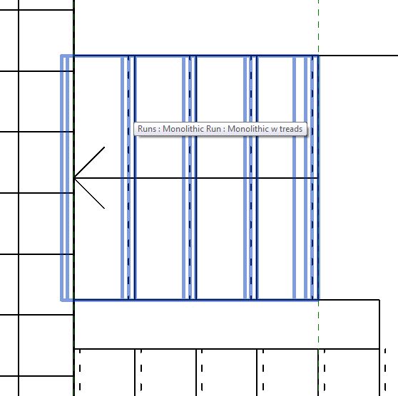
Changing the Discipline of the view to structural, makes no difference to stairs.  Hiding various stair subcategories will not show the hidden concrete underneath, whatever you try.  If you hover the mouse over the run (and tab to get just a run), it highlights the actual 3D model with all the hidden lines available - but they disappear as soon as you select it - how tantalising!
Pre-select run shows hidden lines of concrete below

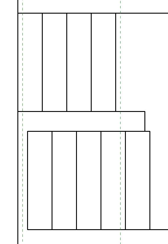
If you hide the floor finish at the top of the stair (in this example it is modelled as a separate floor) you can see that there appears to be a gap - this is because Revit stops drawing the plan where it expects the top nosing line to be rather than where the top riser is (even though it does not model the nosing if your stair 'Ends with Riser').
Gap at top of stairs when floor finish is hidden

Back in the section view, if you turn off the 'Treads/Risers' subcategory it leaves just the concrete substructure.

Notice that the concrete actually extends to the back of the riser in section (and 3D) but this is not shown in plan.  The section also has a couple of other issues:
  • The concrete at the top of the stair stops in line with the back of the top riser, where in fact it should extend up until it meets the underside of the floor slab.  Obviously the stair has no knowledge of where that slab is or how thick it is, but there should be a way to deal with this.  There is a Run property for 'Extend Below Slab' so why not have one at the top.
  • There appears to be a joint between the landing and the upper run even though they are the same material - in fact it is a step in the landing because the concrete landing edge aligns with the nosing rather than the concrete riser.  This would need to be manually adjusted if you want them to align or if you want a finish applied to the landing edge.
Concrete Section - treads/Risers hidden
This is getting close to what a structural engineer might want to see, or for an architectural concrete setout drawing.  So how do we get this to display the same information in plan, when Revit really does not want to do so?

As a workaround, we could try using one of Revit's really weird features, as described in my post about stair arrows and detail views:

Detail view callout

Create a detail view callout of the stair.

This type of view (Detail plan view) is actually a true 3D view (a horizontal section), which does not use the normal Revit 2.5D representation of stairs (and ramps).  The stair shows the top riser line (including thickness) and the actual nosing locations where modelled.  In the snapshot below the floor finish is hidden so you can see the top riser.
Stair in Detail plan view type

So now it follows the subcategory rules that normally apply to a section:
  • Nosing Lines, Riser Lines and Outlines are not relevant to this view type
  • Treads/Risers subcategory does apply - try changing the colour override to test it
Treads and risers overridden in detail plan view

Now try turning off the visibility of the Treads/Risers subcategory - and magically you can see the concrete underneath, because that is controlled by the overall 'Stair' category.

Of course there are some downsides to this method of creating concrete setout plans - Detail plan views are not normal Revit views:
  • You cannot place stair path arrows on detail views (although you can place stair numbers)
  • You cannot 'Reference Other View' callouts to regular plan views - so you would have to work out your view referencing carefully.
  • Detail views do not have a 'View Range', so you have to rely on the parent view or 'Far Clipping'
  • View cut plane is controlled by parent view - and cannot be overridden
  • You cannot use Plan Regions
  • If someone deletes your parent plan view, Vamoose detail view.
  • the list goes on . . . . .


Refer to  True 3D RCP View of a Stair in Revit for more uses of this technique
Refer to stair arrows and detail views for more detail on the downsides of this technique
Go to Revit Stair & Railings Index Page