One of the
new features in Revit 2017 that I am most excited about is "Tangency Locks". The reason is that I have spent many hours, days and weeks trying to control arcs in Revit. Now we have another tool to help with this.
Help
The Autodesk Revit Help files state:
"
Tangency locks: When sketching in the Family Editor, you can now place tangency locks to model lines, symbolic lines, reference lines, or sketch lines. This enhancement eliminates the prior need for complicated formulas and parametric associations to drive tangential relationships"
What on earth does that mean? If you have tried to parametrically control arcs in Revit sketches, you might have some inkling, but otherwise how would you know what a 'tangential relationship' means - it could be something quite intimate if you misread or mistype it!
The
'Whats New' help file neglects to mention that Tangency Locks can also
be applied to system family sketches in the project - floors, ceilings
etc.
If you delve into the details of the help files it explains how a tangential lock can be applied - it even has a little diagram, which is a rarity in the help files. However, it does not actually explain what they do or why you might use them.
The easiest way to describe it is to look at an image of what might happen to a modified sketch in Revit
without a tangential relationship. Here is a Revit sketch with transitions from line to arc to line where each transition is a perfect tangent:
 |
| Tangential transitions from line to arc to line |
So what happens when the sketch is modified? Well that all depends on what the relationships are between each element - what is constrained and how; what is aligned and locked to what else. It is not easy to know or predict. Sometimes the relationships or constraints are obvious - maybe the little lock symbol shows when you select a line, or there is a dimension, which shows a lock symbol when you select it. These are 'Explicit' constraints, because someone made the effort to set them up. There can also be 'Implicit' constraints that are hidden away in the system - Revit follows certain mysterious rules in managing this. For example, lines/arcs that are placed close to reference planes often become associated with them and follow them if the reference planes are moved. How does Revit maintain those relationships? Well, it has some hidden dimensions, called 'Auomatic Sketch Dimensions' - if you switch their visibility on, it often explains a lot about why your Revit sketches behave as they do.

In the above example, let us assume that the joint between the top line and arc is locked to the intersection of reference planes, and that the arc radius is locked. If the other line is moved, the first tangential relationship cannot be maintained without breaking some constraint - so we get a non-tangential relationship. The second tangential relationship may or may not be maintained - in this example it is.
In the example above, if you wanted both ends of the arc to remain at tangents to the straight lines, something would have to give way - either the radius has to change or the locks to the reference planes would be lost. This is important to understand when looking at the new feature of Tangency Locks.
Tangency Locks
In previous versions of Revit, it was possible to retain tangential relationships, but in order to do so we had to undertake some serious trigonometry to calculate where the centre of each arc would be, and then the start and end points of each arc. If the lines are not orthogonal, it gets much more complicated, and pretty soon gives you a headache.
 |
| Formulas - trigonometry to maintain tangents (a simple example) |
In 2017, we now have the ability to click on a tangency padlock symbol to enforce each tangential relationships. Sounds easy - and it is; but you need to think quite carefully about what you are doing, and what might subsequently happen.
As soon as you click on one of those padlocks, it has a knock-on effect to the other ends of the line and arc (or two arcs) - when a line with a tangent lock on it is moved, the tangent is retained, and maybe another line is moved or a constraint has to break
Tangent locks are very strong! They seem to
trump everything else. Or perhaps that phrase is now too political? I should say that they over-ride other locks and constraints. If you are editing a sketch and move something that has tangency locks on it or adjacent to it, Revit may tell you that a constraint is broken, or it may just move something that was previously in a stable location (prior to adding the locks). For example, if you rotate a sketch line about its start point, and that start point has a tangency lock to an arc, Revit will rotate the line as you asked it to do but it will also
move it to maintain the lock - it is logical but may surprise you.
Lock Display
When you select a line within a sketch, Revit will display padlocks for
all the alignment locks within the sketch - very useful to see them all at once (even if a bit messy sometimes). However, tangency locks will only display when you select a line or arc that has locks on it - so you cannot see all of the locks at once. Selecting multiple arcs will cause
no locks to be displayed.
It is important to note this difference, as it may be very hard to track down the tangency locks. 'Reveal Constraints' does not help with this, as it does not show constraints within a sketch.
Example 1
Here is an example of 'before and after' applying tangency locks on a sketch:
- In this sketch a parametric angle has been set up to control a reference line. The angled sketch line is aligned and locked to the reference line.
 |
| Sketch with no tangency locks - before angle change |
- When the angle is changed, Revit maintains the arc radii, and the alignment lock - so what breaks is the tangencies. The end result is horrible!
 |
| Sketch with no tangency locks - after angle change |
- In v2017, tangency locks can be applied to each end of all the arcs. In this example, all of the straight lines are aligned and locked (to references or have locked dimensions). So what changes when the angle is modified is the radii of one of the arcs (top left).
 |
| Sketch with tangency locks - after angle change |
- This works fine for various configurations, but not all
- Eventually something breaks - in this case it is probably the line on the right becoming less than 0.8mm long. The warning message is not very explicit when you expand it, although you might be able to track its ID.
- If this error occurred within a family in a project, it would just say that it could not create type - so you need to do a lot more testing and flexing of families that have tangency locks.
Example 2
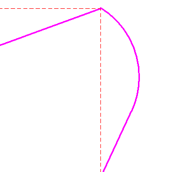
In this example, the end of one line is adjusted so the line changes angle - and the arc is extended to maintain the tangency. However, the radius is reduced to compensate.
I complicated the
simple sketch above a little more by adding parameters to the radii,
and it had some unexpected consequences: it had a knock-on effect all
along the sketch. It can completely move lines on the sketch way along the chain beyond the tancency lock.
When the end of the right hand line is moved in, the radii change, even though they are supposed to be controlled by a parameter, and the left hand line moves in
When the end of the right hand line is moved out, the radii increase, and the left hand line moves left
Move the end of the line a bit further and the sketch goes crazy:
I guess we need to figure out a way to actually lock the radius parameter. Or perhaps it is a bug?
Conclusion
If you apply tangency locks to an old sketch, you may find that you introduce all kinds of constraint problems, so you need to test and flex it immediately after applying the locks - this will hopefully allow you to understand the effect of the locks. You might then find that lines may move, or radii change where they were previously stable - so you might need to add some more constraints or locked dimensions. The more tangency locks that you apply to a sketch, the more testing you need to do - to make sure that you have not introduced new constraint problems. However, it should mean less trigonometry that you need to do!
I think that we will have to get used to a different way of managing constraints in sketches - it might be a little frustrating at first but I'm sure that the pain will be well worth it, and a lot of time should be saved in the future.


