BILT Speaker

BILT Speaker
RevitCat - Revit Consultant

Saturday 19 October 2013

Inuagural European Revit Technology Conference September 2013

Having recently returned from the inuagural European Revit Technology Conference I thought I'd give a quick report on how it all went.  Having been to all the RTC events this year, and all but one RTC ever, it was interesting to compare this event with others.
RTC2013eu_header_896x194

The Venue

Firstly, the venue was amazing - a mixture of old and new in the historic city of Delft in the Netherlands.  Delft looks like a miniature version of Amsterdam but without the swarms of tourists - very old Dutch gabled buildings lining canals.
  • The welcome function was in the Lambert van Meerten Museum, the setting of one of Vermeer's famous paintings.  We were welcomed by a representative of the City of Delft who demonstrated an extraordinary aerodynamic umbrella that was invented in Delft.
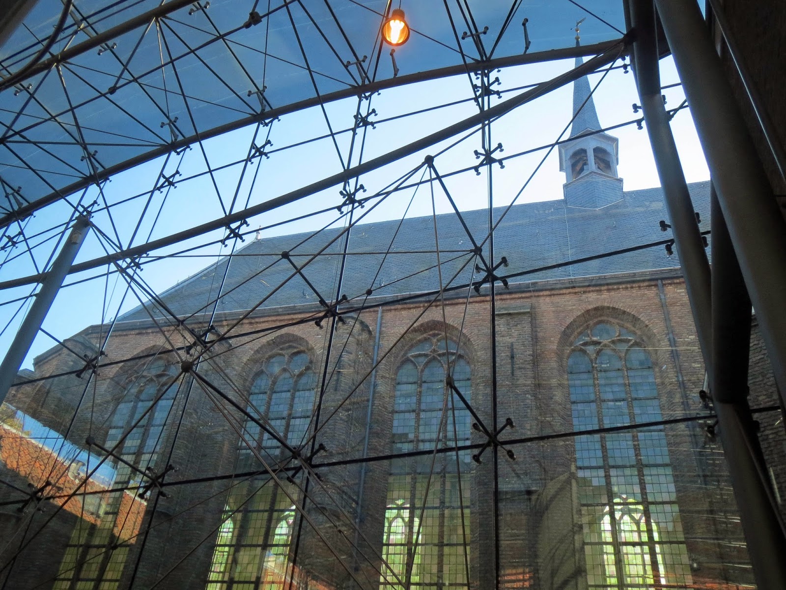
  • The main venue was the Waalse Kerk - a beautiful old church.  There we enjoyed the spectacle of Wesley Benn speaking from the pulpit (sorry he isn't in the pic below).
  • The breakout / exhibition space was adjacent to this in a very elegant high-tech glass enclosed courtyard - they really know how to mix old and new buildings well in Europe (I've seen a lot of this sort of stuff in Belgium and the Netherlands).

  •  The second presentation venue was the Meisjeshuis, just down the canal - well, it was a few minutes walk away beside the canal.  Once a nurses home and then a girls orphanage, it has now been converted to a conference venue.
The walk back to the main venue was a bit scary on two counts:
  • The alarming lean of the tower on the old chuch - looking as if it would topple over onto the Waalse Kerk any minute;
  • If you were too busy looking at the tower you could be knocked into a canal by one of the multitude of bicycles hurtling along the streets.  Talking of which, how do those cars park so close to the edge without falling into the canals.
  • Mind you, if your car goes into the canal there many bikes to choose from - they even have double-decker parking at the railway station.

The Conference

Very sensibly the inaugural conference for Europe was kept small - this made it feel more intimate, like the earlier RTC events.  There were not so many session to choose from, thus making decisions was not as agonising - only 3 instead of 6 or 7 concurrent sessions.  Even so, I still missed one or two things I'd liked to have attended.  The two day length seemed so much shorter than other RTCs - it was over so quickly.  Hopefully it will expand to 3 days next year, now that it has proved to be such a success in Europe.

Speakers were very international - from Europe, North America and Australasia.  Attendees were from all over Europe, but there were large contingents from Norway, Denmark (one company sent 7 people!), the UK and of course the locals (The Netherlands).

The Day Families Became Self-Aware
One of the highlights for me was the session presented by Matt Jezyk  - "The Day Families Became Self-Aware" - an intriguing look at what might happen to Revit families in the future.  In this session Matt started off talking about how useful it would be if families were able to react to their Revit environment - for example, a door that is hosted in a fire-rated wall might need to enable its own fire-rating and change its panel thickness and materials etc.  Currently this is a very manual process for the user having to swap out the door type  (although we do now have reporting parameters that allow us to make the door respond to wall thickness).   Matt then talked about the whole process of API and Dynamo/Python scripting where it is possible to make Revit do all kinds of things, being driven by external code.  However, scripts and API have to be initiated by the user - they cannot react to stimuli or changes in the Revit model itself, so we are still reliant on the user again.  This is all stuff that we know about or are starting to learn of.

Then the exciting stuff started - Matt proposed a type of scripting that could automatically run itself as a response to when a change is made in Revit.  He showed us a prototype of Revit families that contained Dynamo or Python scripts - these families could be placed into Revit models as normal.  When placed the family would run the script and change the component according to where and how it had been placed, for example a door hosted into a wall could check its fire-rating and adjust itself to suit.  Not only that, but if the wall was to subsequently change, the hosted door would re-check the fire-rating and respond again.  So, no user intervention or checking is required.  Wow!  My reaction to that was the same level of excitement I had when I first saw Revit automatically change a drawing reference when a sheet was renumbered:  I want it, and I want it now!!!

Needless to say, this was only a proof of concept, so there is no guarantee that it will ever be implemented in Revit.  Of course it takes quite some time for something like this to reach the market, supposing they do go ahead with it - lots of testing and checking needs to happen.  However, the buzz that was generated in the conference after that was quite noticable.  I was only sorry I was not able to attend Kelly Cone or Martijn de Riet's concurrent sessions - but this was unmissable stuff.

Fractal Fun with Revit Repeaters and Adaptive Components
Photo by from twitter


My own presentation went well - incorporating some improvements since last time. 
It started off showing some fun stuff with Fractal theory and example patterns in Revit:
Fractal patterns - source Wikipedia
Koch Snowflake - source Wikipedia
Fractal Triangles created in Revit


Fractal Trees created in Revit
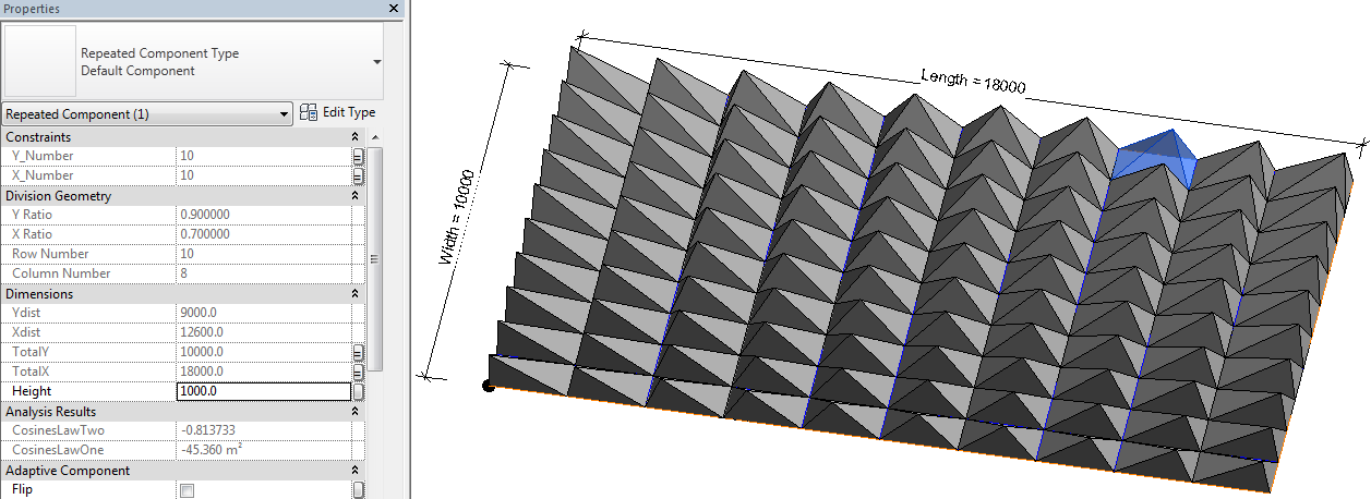
After the fun I demonstrated a few practical examples of how to use nested repeater patterns in Revit, including a picket fence that follows the contours of a site toposurface.
Adaptive fence component with nested repeaters - follows contours

Following this was a less practical but still useful example of how to nest repeater patterns inside curtain panel pattern components in order to force Revit to trim the edges of repeater patterns (which it normally will not do):


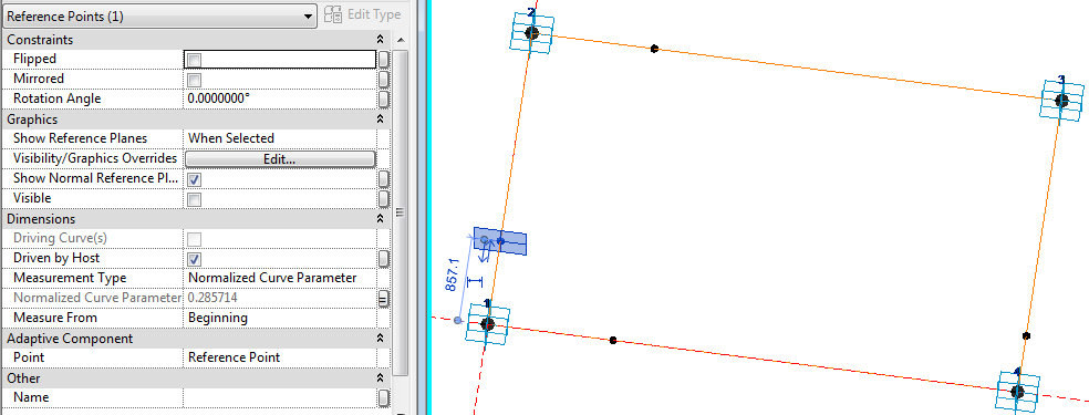
Then came the demo of creating a Revit model of the roof of Santiago Calatrava's Gare do Oriente in Lisbon.  This consited of multiple repeater patterns nested three levels deep, which allowed the creation of very a flexible parametric model with minimal use of maths
Repeater one - one-eigth segment of column with variable number of struts
Repeaters two and three - segment rotated/mirrored around its centre

Repeater four - column assemly in two way array over station platforms
Roof assembly at Revit-Dusk
All of this was done as a live demo in Revit, albeit with some partially prepared sample files in case it didn't work under the glare of an audience.
Photo by Martin Romby - from Twitter
 Roll on RTC Europe in Dublin in August 2014.

Thursday 17 October 2013

How to Schedule Panel Locations on a Flat Rectangular Surface in Revit


This post demonstrates how it is possible to schedule repeater component cell numbers on an orthogonal pattern within the Revit Conceptual Massing or Adaptive Component environment:

To set this up, first you need a rectangular surface, which has been divided; then you need to place an adaptive component onto the node(s) of the surface; once arrayed in two directions using the repeater function you can schedule the cell (column and row) numbers on the divided surface.  Of course it isn't that simple - the adaptive component has to be aware of its location relative to a fixed point, by doing some calculations:
  • The example here is perhaps a little more complicated than it needs be to demonstrate the principle, but it does a few other fun things too.
  • The adaptive component to be repeated must be set to “Shared” so it can be scheduled;  it needs to use shared parameters so they can be scheduled too.
  • In this case it is a 5 point adaptive – one for each corner of the base of a rectangle placed on each cell of the divided surface;  the fifth point works as a “Reactor” – it tracks the distance of the component from a base point.
  • This rectangle is made more interesting by having a pyramid on top that has an apex that moves depending where it is in the repeater pattern.
To create the adaptive component:
1.  Start a new generic adaptive family.
  • Place four points in a rectangular shape;  make them adaptive
  • Join the four points with reference lines (make sure 3D snapping is on)
2.  Set up the geometry for the pyramid (optional):
  • Place a point on each line  (if correctly hosted it displays as a small point)
  • For each point assign a (Shared) parameter to its “Normalised Curve Parameter” – for the notional Y axis point, make it “Y_Ratio”;  its point on the opposite side will have its “Measure From” value set to End, rather than beginning, so that they line up.
  • Assign a parameter “X_Ratio” to the notional X axis points (one from beginning, one from end, depending on which direction you drew the reference lines)

  • Join the two opposing points with reference lines
  • Place another point on one of the linking reference lines
  • Select the point and the option bar should show:
 

  • Click on “Host by Intersection”, then select the opposing reference line;  it should move to the intersection of the reference lines
  • Set the “Show Reference Planes” property of the point to Always.
  • Set the work plane to the horizontal plane of the hosted intersection point (it only shows as a single line)
  • Place another point on top of the one on the intersection (ensure 3D snapping is on);  ignore the error message about duplicate points;
  • Select the new point and drag it up in the zed axis – its ”Offset” property should change.  If you are lucky, it should be a positive value (if it is zero, then the workplane or hosting went wrong);
  • Assign a “Height” parameter to it – if it was a negative value you’ll need to assign an interim parameter then convert it to positive with a formula, for the end user to understand.
  • This point becomes the apex of the pyramid;  
  • Join the point to the four corners of the base with four reference lines;
  • Flex the X_Ratio and Y_Ratio and Height parameters
  • Create a Form (surface) on each of the four sides of the pyramid
3.  Setting up the “Reactor” controls (Important):
  • Place a fifth adaptive point to the left of point 1 (bottom left corner of rectangle)
  • Use a reference line to join it to point 1
  • Join points 5 and 4 (Bottom right corner of rectangle) with another reference line – to create a triangle of lines.
  • Place 3 dimensions between the adaptive points 5 & 1, 1 &4, 4 & 5 – for each one make sure to set the relevant reference line as the work plane for the dimension;  it is vital to snap the dimensions to the adaptive points, rather than to line ends, surface corners etc (if not then you can’t use the dimensions later on in formulas)
  • Make each dimension as a reporting instance parameter, for use in the “cosine law” in trigonometry.  We need to calculate the angle in the triangle
  • The Cosine Law for calculating an angle when 3 sides are known, is:
    Angle γ = Arcos( (A² + B² - C²) / 2AB)
  • Revit version of Cosines formula:
    Angle γ = Acos( (A^2 + B^2 - C^2) / 2*A*B)


  • To work out the X and Y components of the distance “A” between points 5 and 1, use trigonometry:

  • This calculation assumes that the angle of the line between P1 and P4 is orthogonal – so it only works with a rectangular repeater pattern.
4.  Calculation of column and row numbers:
  • This requires knowledge of how many rows/columns there will be in the repeater, and the overall size of the repeater


  • Parameters for these need to be built in to the component as shared parameters (for scheduling), as shown below;  these can subsequently be linked to the parent family parameters for these values.
    X Number and Y Number should be integers (count of repeats in each direction)
    Column Number and Row Number should also be integers.
    X Ratio and Y Ratio should be number parameters
  • You may need a couple of checks to take care of when it has zero values for the distances.

5.  Creation of the repeater:
  • The pyramid family needs to be loaded into another family that can support a divided surface – this could be an adaptive component, a mass family or an in-place mass family in a project.  In this example it will be an in-place mass family.
  • Load the pyramid into the project
  • Start an in-place mass family
  • Draw a rectangle of reference lines,
  • Give the rectangle dimension parameters of Length and Width
  • Generate a form (surface) from the lines
  • Select the surface and Divide Surface 
  • Make the nodes visible on the surface (Surface representation)
  • Assign parameters to U Number and V Number on the surface
  • Place a point just to the left of the bottom left corner of the surface – this will become the control point for measuring distance.  It is important for getting the “Reactor” effect working.
  • Place an instance of the pyramid component by snapping the first four placement points onto four adjacent nodes in the same order as you originally created the adaptive points (say clockwise);  place the fifth point on the external point – it is vital that it does not go onto a node of the surface

  • Link 4 parameters to equivalent parent parameters:
    Y_Number to     V Number
    X_Number to     U Number
    TotalX  to  Length
    TotalY  to  Width
  • Hide the nodes on the surface (Using Surface Representation - they cannot be controlled by any view settings)
  • Select the free control point and move it very close to the bottom left corner of the surface.
  • Select the Pyramid and turn it into a repeater 
  • All being well, the pyramid will array itself over the whole surface, but each instance will look slightly different as the apex point is changed depending on its distance from the control point in the bottom left corner.  If not, it could be caused by a problem with the component itself, or else the fifth adaptive point might be hosted on the same point as adaptive point one, in which case it would move with it.
  • Select (tab) any one of the pyramids;  it should display properties including its correct column and row number

  • Finish the in-place mass family
6.  Create a generic Schedule:
  • Add the column and row numbers, and any other parameters you require
  • You will be able to edit the values for Comments and Mark, but no other instance values
  • If you edit the mass family, it allows you to manually select any of the components in the repeater.  Then you can set it to “No Component” or to any other 5 point adaptive component.
When you edit the mass family, the schedule temporarily goes blank.  Sadly this means that it is not possible to drive the geometry from the schedule.  However, it does make it easier to identify and label components in a schedule – useful for adding and editing Mark values to match column and row numbers.

This technique will not work with a curved surface because it all works by calculating the actual distance from the control point to the BL corner of the pyramid and relating that to the overall length of the surface.  It will only work on an orthogonal divided surface, unless you are a mathematical genius and can write formulas to handle more complex geometry!