BILT Speaker

BILT Speaker
RevitCat - Revit Consultant

Wednesday 23 September 2015

Weird Revit Railing Stuff - part 6 - SubCategory Overrides

I was recently asked to solve a tricky Revit railing puzzle:  Someone wanted to show their glass panel balustrade as semi-transparent in elevation.  Simple, you might think.  Think again.
All good Revit experts would know that any element with a glass material that has a (semi-)transparency property will display transparent in a 3D view, but in elevation or section it shows solid.
Glass transparent in 3D view

Why is this?  Because it has always been an architectural drafting convention to make window glass opaque in elevation, so you cannot see through windows to all the stuff inside.  This is pretty sensible as elevation drawings would look a terrible mess otherwise.  So this convention was hard-coded into Revit software, as were many other conventions that we now see as restrictions .  Unfortunately this also applies to any glass element - even a glass balustrade that hides vital information behind it on a balcony.
Opaque glass balustrade in elevation

The obvious solution is to make either the railing category or just a selected railing semi-transparent

Semi-transparent Railing category override
But that is not much use as the handrail and balustrades have become transparent too.  So what about the railing subcategories?  Unfortunately the actual subcategories do not have individual transparency overrides - it is all or nothing for the whole category.
Railing subcategories in Visibility Graphics
 In addition to that, if you wanted to override the surface patterns there are some random restrictions:  some new railing sub-components allow overrides, some don't;  the old railing components do allow surface pattern overrides.
  • Balusters (old subcategory) - Yes
  • Rails (old subcategory) - Yes  - these are the original horizontal rail structures
  • Supports (new subcategory) - Yes
  • Terminations (new subcategory) - Yes.  Great, I can override the surface pattern but there is no possible way to make them visible in plan.  how good is that?
  • Top Rails (new subcategory) - No!   This is a newly added subcategory (in 2013), so why build in a restriction to the subcategory most likely to need an override pattern?
Most experienced Revit users would not attempt to create glass balustrades using 'Balusters' because they are almost impossible to control the spacing of (and width).  Instead they would use the old rail subcategory and have one rail for the handrail on top and another long tall, skinny glass rail for the balustrade (crashing through the actual support balusters).

Filters

Next stop view filters to see if the same restrictions apply.  Perhaps we could filter the glass rail separately from the top rail structure?
More inconsistencies here:  Balusters (old subcategory) can be filtered, but not the old Rail subcategory.  Foiled at the next turn by yet another inconsistency.  But this time all the new subcategories can be filtered, including 'Top Rails'.  So maybe we could (mis)use that for the glass balustrade, and create a view filter for the Top Rail only?
 You could even take it one step further (no stair pun intended) and restrict it to Top Rails with the word 'glass' in them.  Note that I have used the filter "contains" rather than "equals" as it would then find all types with that word in the name.  To make it more robust, you could filter by "contains" "lass" so that it would pick up lower and upper case glass and Glass types.
Once the filter is set up, it needs to be applied to the view, and then have its transparency override set

All that remains is to make sure the railing definition is set to use a 'Top Rail' for the glass balustrade, and a 'Rail' for the actual rail along the top.


And finally it works as desired - but it shouldn't be this hard to achieve.
Semi-transparent Top Rail subcategory for glass balustrade

A gold star to anyone who spotted that the swing symbolic lines are broken on the doors behind the railing.  Not my doors, I just grabbed them from an old library to demonstrate this issue!

Sunday 20 September 2015

RTC Asia 2015 wrapup

Presentation on Best Tall Building - Documented in Revit
I arrived home a week ago after attending the inaugural Asian Revit Technology Conference (RTC) in Singapore - another great success from the RTC Events team.  Attended by over 200 people from 23 countries - many from Singapore.  The conference was held in the Equarius Hotel on Sentosa Island, which has been turned into a giant resort island - a big change from when I last visited. Then it was a remote jungly part of Singapore only accessible by cable-car.  Singapore was very hazy - shrouded in smoke drifting across from forest fires in Sumatra (probably deliberately lit to clear land for palm oil plantations).  It made outdoor photography difficult, but it didn't hold the conference proceedings back, as the typically over-cooled air-conditioning took care of that.  I attended several very interesting sessions, and as always I learnt new things about Revit.

The Friday evening function was held at Tanjong beach, and inevitably a number of RTC committee members ended up in the swimming pool by the end of the evening.
The gala dinner was held at the Park Royal Hotel, designed by WOHA - a very interesting 'open' design that incorporates a large amount of greenery at various levels of the building (more than the site area).

The pods suspended out from the swimming pool create interesting private spaces as well as adding some drama

There was a fabulous spiral stair leading from the lobby up to the function areas - 50 steps in one run, without a single landing.  Not sure how they were allowed to do that? 


But at least they had handrails, unlike one spiral stair I saw in Sri Lanka the previous week - perhaps they were so frustrated by trying to model Revit railings they just left them off?  Not much fun if you are scared of heights!
Near Ahungalla, Sri Lanka

Friday 4 September 2015

Perfect Stair Railing Transitions at Half Landings

I am currently in Sri Lanka en route to the inaugural Asian Revit Technology Conference in Singapore - RTC Asia 2015 at the Singapore  from 10 - 12 September 2015.  If you can possibly get to RTC in Singapore next week you really should do so - you will certainly learn a lot about Revit and/or BIM, regardless of your skill levels.  Your investment in the conference will pay for itself many times over.

The reason for my current detour is to do some research for the conference - to learn from one of the great masters of architectural detailing, renowned Sri Lankan architect Geoffrey Bawa.  He has designed many beautiful buildings by perfectly managing spaces, repeating patterns and a great attention to detail - all with an elegant simplicity.


At the conference I will be presenting a lab session on stairs and railings (afternoon on day one), so I have been paying close attention to handrail details.  Some of Bawa's details are very chunky, as per the style of the time - but they still look good several decades later.


Sometimes Bawa's details are less elegant than whimsical - in fact can be downright scary, but those examples are few and far between: 
5-headed cobra handrail termination
Now that would be a challenge for Revit to model as a handrail termination!

Railing Transitions

Handrail transitions at half landings have always been a problem for Revit to achieve neatly, but with the changes to railings in v2013 the situation actually got worse - if you try to use the new Top Rail or Handrail features.  Revit seems to require lots of extra horizontal space to make the turns - as documented previously - Top Rail Transitions and Top Rail Offsets

Geoffrey Bawa detailed his handrails to transition perfectly where they turned a corner without the extra horizontal lengths that Revit insists on, as seen below:


Revit Transitions
Bawa Transitions


If Bawa and his craftsmen could do it perfectly, why can't Revit?  Revit should learn from a great master.


Thursday 3 September 2015

Weird Revit Stair Stuff - Stair Path Arrows in Detail Plan Views

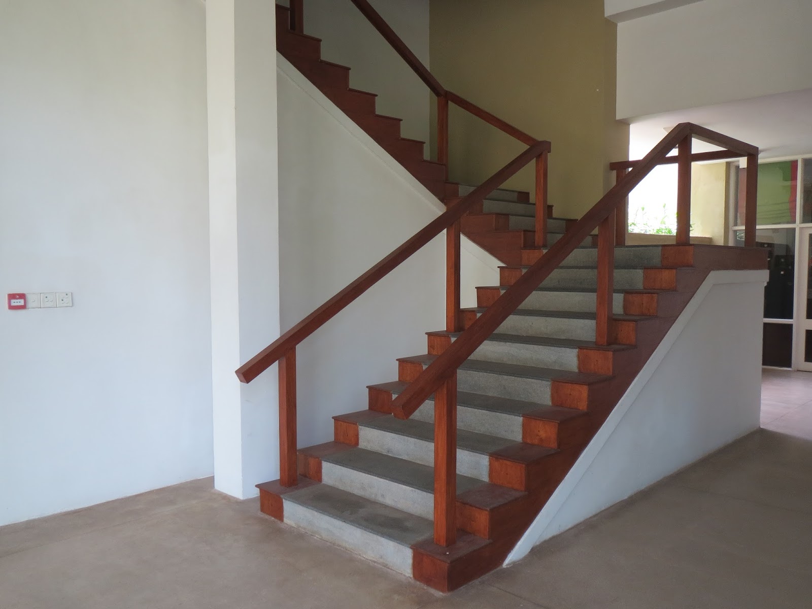
Here is yet another inconsistency with the (not so) new Revit stair tools.

If you want to create a stair detail drawing, you might start off with a general arrangement plan that has a reference to a stair plan at say 1:20 or 1:50.  Good Revit methodology might suggest creating a callout from your general arrangement plan to generate the stair plan. .  If you do that, the default view type that it wants to create is a "Detail Plan View" - so most people would probably go with that option, without giving it another thought.  Bad move!

Here is where the inconsistency catches you out:  After spending hours setting up the stair sections and annotation on the stair plan, you realise that the stair path arrow is missing.  So you try to place a new one . . . .
Aaaargh!  It is greyed out - so you cannot place a new stair path arrow on your stair detail plan.  However, you can place stair numbers on a component stair in a detail plan view (but not on an old style sketch stair).

Why is this?

2.5D vs 3D 

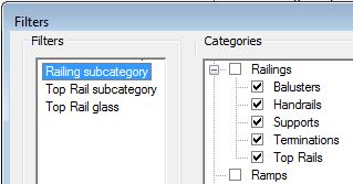
I believe that it has to do with how a Revit "Detail View" is created:  unlike any other Revit plan view, it is a true 3D section through the model that is cut horizontally.  Other plan views are really only 2.5D because Revit uses all kinds of tricks and shortcuts to represent certain elements in a more traditional plan format rather than a literal slice through the element.  Stairs, railings and ramps are all special element types that have a system controlled 2.5D way of presenting in plan when cut. 
Other categories that might not show true 3D representations would be 'non-cuttable' categories such as furniture ad specialty equipment - they just show a top view.
On the other hand, categories like floors will show a true 3D representation when cut in plan - clearly demonstrated when you use a sloping floor instead of a ramp.
Detail View callout - literal 3D cut plan

Floor Plan callout - 2.5D plan representation

However, all of the above is no excuse for the software developers not to fix the issue so that you can put a stair path arrow in a detail view.

How to solve it?  Well you could just use a line-based detail component (with a built in arrowhead).  But your railings and stair cut lines won't look right either, so you start needing to add break lines, masking regions etc.

There is a better solution:

Plan view vs Detail View

In my opinion, you should just avoid using Detail View types for any plan details.  When placing a plan callout, you should always set the view type to Floor Plan - preferably to a pre-defined type that you have created for specific sorts of details.  Unfortunately Revit keeps reverting back to the Detail View type as its default.  If you forget to set this correctly when creating the callout, you are in trouble as it cannot be changed later.

There are many other reasons for doing this aside from fixing stair plans:
  • Detail views have significant limitations on where and when they can be referenced (see below).  Eg. On a ‘Detail Plan View’ you cannot reference a normal plan view;
  • You cannot change a detail view to a plan view (or vice verse);
  • Plan view callouts allow a different view range to the parent view; detail views have a far clipping offset, which is confusing and does not allow a different cut plane
  • In the Project Browser, Revit groups all Detail Views together (plans and sections), in quite a different place from normal plans - so if you use a mixture of Floor Plans and Detail Views for plan details it becomes a nightmare to organise and find the views.


Reference Other View

In V2016, rules for 'Reference Other View' for callouts are:

In a floor plan view, you can callout 'reference other view' to

  • Any drafting view
  • A detail view callout
  • A floor plan callout (but not a regular plan view)

In a Detail plan view, you can callout 'reference other view' to

  • Any drafting view
  • Any detail view callout
  • Not to any floor plan callout - (this is a big limitation)

In a drafting view, you can callout 'reference other view' to

  • Any drafting view
  • A detail view callout
  • A floor plan callout (but not a regular plan view)

For more info on these issues: