In my recent
presentation at BILT ANZ 2018 in Brisbane - Creating Nurby Forms in Revit, I started off by analysing how the traditional Revit 3D form creation tools can be matched in the Conceptual Massing Environment.
Traditional 3D form creation in Revit has 5 predefined sketch-based tools – these are well understood by most Revit users. They are also very limited when it comes to creating double-curved or organic shapes.
Unlike these, the newer Adaptive/CME form creation methods (from Revit 2010 onwards) are somewhat of a mystery to many users – the logic is completely different, and there is only one ‘Create Form’ command. However, it is capable of creating much more organic shapes than the traditional tools.
I have previously listed an
extensive comparison between the 'Rival Revit Form Creation Environments'. In this series of blog posts I will go into much greater detail on the subtle inconsistencies between each form creation method. Understanding these 'exceptions to the rule' make the whole Conceptual Massing Environment (CME) much easier to work with - I use the word 'easier' rather than 'easy', because the CME is never easy!!
One of the big differences between the old and new methods is the ability to ‘Loft’ shapes in the CME, or to use multiple profiles in a swept blend:
- The traditional environment allows the creation of a ‘Swept Blend’, which creates a single transition from one 2D profile to another – while this does allow some double curved surfaces, the transition between the two is constant along the path of the swept blend;
- The CME also allows the creation of a Swept Blend along a path, but the big difference is that it allows more than two profiles – this allows the transition to be controlled and changed at any point along its path. There are many ways to achieve this but unfortunately Revit has a number of significant limitations in what kinds of forms it will create (more on this later).
- The CME ‘Loft’ function allows the use of multiple shapes/profiles to control the transition from first to last, without selecting a path.
There are many more differences that will be described in the following posts.
CME shape creation methods
The CME Create Form function only has one icon, with no user controlled options - and it works in several different ways, depending on what elements you select:
- Single shape/profile (chain of arcs/lines/curves) – creates an extrusion of the profile. It can be an open profile that creates a surface, or a closed profile that creates a solid form, in which case it puts end surfaces on the extruded form
- One profile plus a path - creates an extrusion or sweep (can be multiple segment path for closed profiles)
- One profile plus a separate straight line - creates a revolve
- Multiple profiles plus path – creates a swept blend (single element path only)
- Multiple profiles without path – creates a loft form
- By hosting elements along a path then selecting all the elements (but not the path) – it creates a hybrid swept blend / loft
It is not clear to the user how Revit decides which creation method to use and how it decides which element defines a profile, and which is a path or axis, nor the order of multiple profiles. This is the crux of the problem - in simplifying the User Interface to a single command icon, Autodesk have robbed the users of predictability and real control over the end result.
Some of the problems could be alleviated by the following two capabilities - please vote for them on the Revit Ideas wish-list if you agree:
Control profile order during form creation
Nominate Path during form creation
Traditional Methods in the CME
Each of the traditional form creation methods (plus lofting) are examined in the Conceptual Massing Environment in the following blog posts (links will be enabled as each is posted):
1.
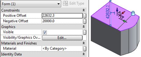
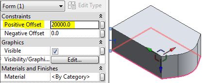
Extrusion
Extrusion Offset Properties
2.
Blend3.
Revolve4.
Sweep5.
Swept Blend6.
Loft7. Hybrid Swept Blend / Loft
Path
The form creation path (if used) can be model or reference lines or edges of another form or component
- Path can be a single arc, line or curve (Revit help refers to all of these as a line)
- Sometimes it can be a multiple chain of elements – for closed profiles on sweeps only
- It cannot be a ‘divided path’ element
Profiles
The form creation profiles can be:
- Model or reference lines (chained) or
- Edges of a form or
- Loaded components - 2D model lines (planar) within a component (adaptive or traditional of most categories, but not a traditional 2D profile family)
- Must be a single chain of lines, arcs, curves (open or closed profile);
- Very occasionally Revit allows a loop within a loop;
Depending on the original profile, the form behaves quite differently - It makes a big difference whether you use Model lines or Reference lines:
- Model lines are ‘consumed’ by the form and can be edited later (Edit Profile);
- Reference lines are retained as an underlying rig for the form – and they can be independently edited to change the form (can only be moved/stretched);
- Reference line extrusion forms are automatically locked; model line extrusion forms are not;
- Component profiles are not consumed, and can be changed if parametric;
If you host points onto a path, and then host profiles on those points (as recommended by Autodesk), there are differences in behaviour once a form is created from the profiles:
- Model line profiles – the host point gets consumed too. It cannot be selected or moved; it loses any properties & associations to parameters (eg. for offset from end of host path); to move the profile along the path, you have to select it, not the host point – which has no parametric control;
- Reference lines – the host point retains all its properties and associations, so it can be moved along the path parametrically (profile goes with it)
There are other subtle differences, to be explained later - in the individual form creation method posts.
Adaptive components
Adaptive Components are a special kind of Revit family that operate in the CME world (not traditional family editor forms)
- They are similar to Mass families but can have multiple insertion points
- They can be of some different categories (but not mass) – somewhat limited
- Cannot be created in-place in a project
Repeaters
Repeaters are a kind of array, in the CME world
- Made up of adaptive components hosted on divided paths or surfaces within a mass or adaptive family, which are then arrayed using the ‘Repeater’ function.
- Profiles within the repeaters can be used to create forms, with some limitations – the Repeater first has to be dissolved; the divided path cannot be used as a form creation path.