BILT Speaker

BILT Speaker
RevitCat - Revit Consultant
Showing posts with label lock. Show all posts

Friday, 14 April 2023

Zoom in Family Types Dialog Box

Today I watched episode 99 of BIM After Dark, hosted by the Revit Kid.  The guest presenter was  Nicolas Catellier (Revit Pure), showing Advanced Revit Family Concepts.  However much you might think you know about Revit, there is always something new to learn.  

One tip that I picked up was the ability to zoom in the Family Types dialog box - this can be useful when you are editing families on a high resolution screen and the text is tiny.   Editing a complex formula is painful enough in Revit without having to squint to count the brackets at the end of a formula.

Family Editor Zoom

Just click in the Family Types dialog box, hold down the Ctrl key and use the mouse scroll wheel to zoom in or out.


There is one problem with doing this:  it plays havoc with the column widths.

  • The Lock column will most likely no longer fit in the dialog box 
  • A horizontal scroll bar may appear at the bottom of the dialog box

  • If you click in one of the formulas, it tries to display the whole formula column - which is logical
  • It also shifts everything to the left so it can display the Lock column - this is illogical and intensely irritating as you can no longer see the values.
  • You need to scroll left again to see the values

To resolve this you need to make the Formula column a bit narrower, and the Lock column much narrower (width of the checkbox).

It is not immediately obvious how to adjust the Lock column width:

  • Drag (to the left) the right-hand vertical line on the Lock column header - it seems like nothing is happening, but keep dragging it left until you align with the checkbox.

  • Drag the left-hand vertical line on the Lock column header to the right, until just before the right-hand line disappears.
  • You may need to make the Formula column narrower again until the horizontal scroll bar disappears from the bottom of the dialog box - but once you have minimised the Lock column width it should be easier to do that.


For a more detailed explanation of this workaround trick, refer to my blog post of a couple of years ago:

 Family Types Dialog Column Widths

 Thanks again to Jeff and Nicolas for the BIM After Dark presentation.


Tuesday, 15 June 2021

Family Types Dialog Column Widths in Revit

Does anyone find trying to control the column width in the Family Types dialog box annoying?

The "Lock" column in particular, has been driving me mad for the last 16 years!

About 7 or 8 years ago (?), Autodesk made a partial improvement to that dialog box: 

  • Revit remembers the size of the dialog box when you open or close the dialog - previous to that it always reset to a small default size & layout.  
  • However, it still behaves in an unpredictable way, which is intensely irritating.

I just discovered a trick that helps to get around the problem - so I spent a while analysing exactly what is going on:

Family Types Dialog Box Size Behaviour

  • When you close the Family Types dialog, and subsequently reopen it, Revit remembers the overall size and location of the dialog box.
 
  • This also happens between sessions:  When you close Revit, the next time you start Revit, it remembers the size and location of the dialog box.


Family Types Dialog Column Widths Behaviour

If you adjust the column widths in the dialog box:

  • When you close the Family Types dialog, and subsequently reopen it, Revit remembers the widths of the columns in the dialog box (even if you are editing a different family).
  • Not so between sessions:  When you close Revit, the next time you start Revit, it RESETS the widths of the columns in the dialog box to defaults below (albeit within saved overall width).

Default Column Widths:

    • Parameter = 26%
    • Value = 22%
    • Formula = 40%
    • Lock = 12%

Adjusting Column Widths

If you adjust the column widths, it follows strange and annoying rules:

  • Adjust between Parameter/Value:  It changes Parameter and Lock Column widths
    • This is not helpful as the lock column is wasted space!

  • Adjust between Value/Formula:  It changes Value and Lock Column widths
    • Even less helpful as the Lock column gets enormous

  • Adjust between Formula/Lock:  It changes Formula and Lock Column widths

When adjusting Formula/Lock columns, be careful:

  • If the right-hand "Lock" column vertical line disappears, it means the Lock column no longer fits in the overall width - this will cause much irritation (see below)
  • This makes a horizontal scroll bar appear at the base of the dialog box - yuk!
  • If you subsequently put the cursor anywhere in the "Value" column, as soon as you type a value and press enter, your dialog box may do a "crazy leprechaun dance"*
    • The focus moves into the Formula Column
    • In its infinite wisdom (/stupidity), Revit wants to display the column to the right in full - so it moves to show the whole of the Lock Column
    • You will probably no longer be able to see the Parameter name and/or Value

[*NB. this is what the first iteration of the ribbon menus in Revit 2010 was referred to as doing]

NB. This does not always happen - I think it depends on the overall dialog box width and the Lock Column width


Clever Trick

I only discovered this a couple of days ago:

  • Adjust the Formula/Lock column widths as close as you can to desired

  • Select the right-hand vertical line of the Lock column, drag it to the left until the cursor aligns with check-box
    • Nothing appears to happen
    • However, in its mind, Revit is actually making the column width smaller (it just doesn't show the change)

  • Adjust the Formula/Lock column widths again - to the right
    • it lets you get the Lock column width much smaller (without losing the right-hand line)
  • You can make the Lock column tiny - check-boxes will shrink

Once you have made the Lock column very small - it remains proportionally small when you increase the dialog box size - which is really useful.

Workaround to Avoid the Problem

If you always follow these rules, you are less likely to have a problem:

1.  Adjust your dialog box size to exactly what you will need for the entire Revit session - so if you are working with formulas a lot, then allow for a large width

2.  Adjust the column widths in this order:

  • Parameter/Value  <

  • Value/Formula  <
  • Formula/Lock (keep the right-hand line visible) - move to the right  >
  • Right-hand side of Lock column - move it to the left  <
  • Formula/Lock again - move to the right  >


3.  Make sure you never have the horizontal scroll bar visible 

  • If you ever adjust the Parameter or Value column widths, check the right-hand side of the lock column title - make sure it is visible (and no scroll bar).


Conclusion

If anyone tells me that they have known about this for years, I'd like to know why they never informed me before!


If you would like Autodesk to fix this problem, please go to Revit Ideas and vote for the wishlist item that Dave Plumb recently posted.


Monday, 25 June 2018

Creating Blends in Revit Mass - CME Part 2

An earlier post introduced the idea of  comparing the five traditional form creation tools with equivalent techniques in the Revit Conceptual Massing Environment.  Previously we analysed the creation of extrusion forms in the CME.  Now it is the next of the 5 traditional forms:


Part 2:  Blends

In the traditional Revit environment, you have to decide on a blend before you start.  In the massing environment you can do that or decide to create a blend after you have made an extrusion.  The exact method depends on how the profile is created before using it to generate a form.

I have recorded a video description of this process, available on YouTube.

This one is pretty quiet, maybe suitable for an open plan office.  Crank up the volume if you are at home.

Read on if you don't like videos (or you are hard of hearing!).

There are several ways to create a blend form in the CME:


Method A (Unlock Extrusion)

This method assumes that you already have a form created as an extrusion.
  • Select the form;
  • ‘Unlock Profiles’ (if locked)


  • This converts the form into a blend, which has a profile at each end (each the same to start with) – they can be edited separately.
If the original profile was model lines:
  •  Each profile can be edited in sketch mode (Edit Profile command).
 

If the profile was reference lines:
  • The start remains as reference lines, with limited edit capability (move the reference lines) 
  • The end profile can be edited in sketch mode

If the original profile was a component:
  • you can edit the end profile only, not the start profile
  • If the profile family is parametric, you can adjust the form parametrically
  • You can edit the profile family, and the form changes when you reload the family - within reason; if the changes are too drastic, it may fail when you try to reload.

Method B (Create Blend)

Create two parallel 2d profiles (model, reference lines or flat components) ;

  • Select both profiles; 
  • ‘Create Form’
  • Revit will create a Blend form

If the profiles were model lines:
  • You can edit the profiles of each end 


If they were reference lines:
  • You have limited edit capability (move lines)


If the original profiles were components:

  • You can change them (if parametric) 
 
  • Or you can edit the profile family and reload 


The two starting profiles do not need to be parallel.


Related topics:

Monday, 18 June 2018

Extrusion Offset properties in Revit CME

Following on from the description of creating extrusions in the Conceptual Massing Environment, here is another subtlety regarding properties of extrusions in the CME.

Offset Properties 

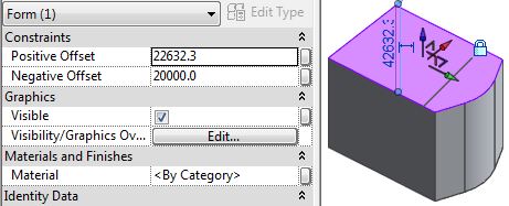
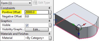
Locked extrusions have 'Positive & Negative Offset' properties, that drive the distance of the end facets from the original profile.  These behave in different ways depending on exactly how the extrusion was created and locked.

Reference Line Extrusions

  • Create Form using reference lines as the profile
  • Creates an extrusion, which is automatically locked
  • The form has Positive and Negative Offsets, relative to the reference lines


  • Select the base facet, drag down

  • Negative offset value
  • Reference lines remain in original position


  • Unlock the extrusion - no offset properties


Model Line Extrusion

  • Create Form using model lines as the profile
  • Extrusion is not locked  automatically
  • Does not have offsets

  • Select the top facet
  • Lock the form to an extrusion
 
  • Padlock does not appear (unless you reselect the form)
  • It now has Offsets, relative to top facet (not the base, which was the original profile)
  • Drag the top facet up and it shows a positive offset
  • The Negative Offset is the position of the bottom facet relative to the original position of the top when it was locked - there is no visible record of that location.
  • Undo
  • Edit profile
  • It does not ask you which profile to edit (as it is locked)
  • Revit goes into Sketch edit of the top facet (not the base, which was the original profile)

  • Cancel
  • If you were to 'Dissolve' the form at this stage, you would end up with only the top facet, which is in a different location to the original profile.
  • Do not proceed with 'Dissolve'; or Undo, if you did.
  •  Unlock the extrusion form (the Offset properties disappear)
  • This time, select the bottom facet (or a line/edge on it)

  • Lock Form
  • Offsets now relate to bottom facet - more logical in this situation

  • Edit Profile
  • Sketch edit is now the bottom facet (original model line profile)


The moral of this tale is that you need to plan very carefully when creating extrusions - first choose whether to use model or reference lines;  If you chose model lines (which allow easy editing of the profile to add/remove segments) then choose a line/edge carefully before locking the profiles.

Conclusion

A real life example of when this would be important is the creation of a 'context' model for your site:
You want to model adjacent buildings as simple extrusions, and you want to control their height by typing in known RLs, without having to calculate heights.
  • As you probably want to work in context in a project, you might create an in-place mass family;
  • However, it could also be done in an external family, as a generic Adaptive Component (with no adaptive points), changed to a site category;
  • Draw the profiles on a Datum level (or reference plane) at RL zero (or round number, say 100 or 1000 metres)
  • Choose model lines for easy profile editing (or reference lines for stability);
  • Create Form
  • Deselect the top facet
  • Select a line on the base
  • Lock Profiles
  • Select the top facet
  • Type in the RL (in mm) for the building height

  • You could also adjust the base facet height using a minus value in the negative Offset property to represent the RL of the base of the building