
Back in Revit 2012 Autodesk changed the way materials work - so that they had separate graphics and appearance properties. This was the start of much confusion for many users - and still to this day it catches people out. You know the drill: duplicate a material; change its appearance properties and suddenly a hundred other materials change too . . . .
Well, I am not going to address that issue directly. Instead I want to look at a more subtle confusion that some users encounter: Exactly how do the different material properties display in each 'Visual Style' - it will not always be what you might expect or consider to be logical
Material Properties
In order to analyse this issue we start with two very simple material definition examples, applied to two elements in a Revit project:
Material 1 - Demo Generic
- Light grey shading
- Light Blue appearance (different colour to shading)
- no surface patterns


Material 2 - Demo Green
- Light green shading and appearance;
- no surface patterns


Visual Styles
These materials display as expected in the various 'Visual Styles' in Revit - because we know that the graphic 'Shading' colour property matches the 'Appearance' colour property in material #2 but not in #1
Material #1 on left, Material #2 on right
 |
| Hidden Line Visual Style |
 |
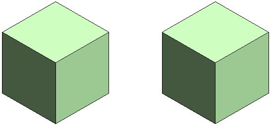
| Shaded Visual Style |
 |
| Consistent Colours Visual Style |
The colour displayed for material #1 (left) in Realistic and Ray Trace visual styles is different to shaded and consistent colours because the material properties do not match - this is to be expected.
 |
| Realistic Visual Style |
 |
| Ray trace Visual Style |
Material #1 on left, Material #2 on right
Lighting
These views are lit with default sun and lighting settings (ie. light source over the right shoulder of the viewer)


Use Render Appearance
One thing that users often forget to address is consistency between the 'Graphics' and 'Appearance' colours. If the colours are dramatically different, then materials look completely wrong, particularly in 'Shaded' views.
There is a quick and easy way to deal with this - it is the 'Use Render Appearance' checkbox to make sure the shaded colour matches the appearance colour.
This property can be used as a one-off operation - ie, tick the box to change the colour, then untick it.
Or you can just leave it ticked if you want the shading to update when the appearance property might change in the future.
- NB. Make sure that the appearance colour is correct first - as there is no 'Undo' so you might lose a shading colour definition.
- Do not use this method if the shading colour is correct but appearance wrong
Surface Patterns in Materials
When you add surface patterns to materials is where things get more complicated . . .
We will make two more materials, based on the light green shaded material - these will use the same light green 'Appearance' (unchanged).
Material 3 - Demo Green Line Hatching
- Light green shading
- Light green appearance;
- Line Cross-Hatching foreground surface pattern

Material 4 - Demo Green Solid Hatching
- Light green shading
- Light green appearance;
- Line Solid Fill foreground surface pattern

Visual Styles
Hidden Line
- Cross-hatch pattern is displayed as you might expect
- Solid fill displays with solid colour - but without any lighting effects
 |
| Hidden Line Visual Style |
Shaded
- Cross-hatch pattern is displayed on top of the shading colour
- Solid fill displays replaces the shading colour - it is completely obscured - this can be confusing if the user has not studied the material properties carefully
 |
| Shaded Visual Style |
 |
| Consistent Colours Visual Style |
Realistic (and Ray Trace)
- Cross-hatch pattern are not displayed at all - unless a hatching pattern is defined within the material appearance (not a simple thing to achieve)
- Appearance Colour replaces the Solid fill colour - this is the reverse of what happens in a Shaded visual style - so it can be confusing
 |
| Realistic Visual Style |
Background Hatching
Just for the record, here is what happens with background hatching - it follows the same rules as Foreground hatching. [NB. This capability was added in Revit v2019]
Material 5 - Demo Green Line Background Hatching
- Light green shading
- Light green appearance;
- No foreground hatching surface pattern
- Line Cross-Hatching background surface pattern

Material 6 - Demo Green Line Foreground & Solid Background Hatching
- Light green shading
- Light green appearance;
- Line Cross-Hatching foreground hatching surface pattern
- Solid Fill background surface pattern

Visual Styles Materials 5 & 6
Material #5 on left, Material #6 on right
 |
| Hidden Line |
 |
| Shaded |
 |
| Consistent Colours |
 |
| Realistic |
Conclusion
Solid Fill surface patterns are the one part of this Visual Style issue that cause display inconsistencies.
You may have good reasons for using Solid Fill surface patterns as part of a material definition - in which case go for it. Otherwise, they are to be used with caution in normal Revit use.
Another approach to avoid the inconsistencies would be to make sure the appearance, shading and solid fill colours all match up.
Don't forget to check how many materials are sharing the Appearance asset before you change it - it is the number above the hand on the Appearance tab.


