BILT Speaker

BILT Speaker
RevitCat - Revit Consultant
Showing posts with label surface. Show all posts

Sunday, 15 August 2021

Display Priorities of Solid Fill in Revit Materials

Back in Revit 2012 Autodesk changed the way materials work - so that they had separate graphics and appearance properties.  This was the start of much confusion for many users - and still to this day it catches people out.  You know the drill:  duplicate a material;  change its appearance properties and suddenly a hundred other materials change too . . . .

Well, I am not going to address that issue directly.  Instead I want to look at a more subtle confusion that some users encounter:  Exactly how do the different material properties display in each 'Visual Style' - it will not always be what you might expect or consider to be logical

Material Properties

In order to analyse this issue we start with two very simple material definition examples, applied to two elements in a Revit project:

Material 1 - Demo Generic

  • Light grey shading 
  • Light Blue appearance (different colour to shading)
  • no surface patterns


Material 2 - Demo Green

  • Light green shading and appearance;  
  • no surface patterns


Visual Styles

These materials display as expected in the various 'Visual Styles' in Revit - because we know that the graphic 'Shading' colour property matches the 'Appearance' colour property in material #2 but not in #1 

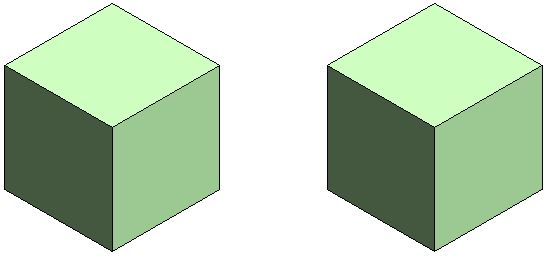
Material #1 on left,              Material #2 on right

Hidden Line Visual Style

Shaded Visual Style

Consistent Colours Visual Style

The colour displayed for material #1 (left) in Realistic and Ray Trace visual styles is different to shaded and consistent colours because the material properties do not match - this is to be expected.

Realistic Visual Style

Ray trace Visual Style

Material #1 on left,              Material #2 on right


Lighting

These views are lit with default sun and lighting settings (ie. light source over the right shoulder of the viewer)


Use Render Appearance

One thing that users often forget to address is consistency between the 'Graphics' and 'Appearance' colours.  If the colours are dramatically different, then materials look completely wrong, particularly in 'Shaded' views.

There is a quick and easy way to deal with this - it is the 'Use Render Appearance' checkbox to make sure the shaded colour matches the appearance colour.


This property can be used as a one-off operation - ie, tick the box to change the colour, then untick it.

Or you can just leave it ticked if you want the shading to update when the appearance property might change in the future.

  • NB.  Make sure that the appearance colour is correct first - as there is no 'Undo' so you might lose a shading colour definition.
  • Do not use this method if the shading colour is correct but appearance wrong


Surface Patterns in Materials

When you add surface patterns to materials is where things get more complicated . . .

We will make two more materials, based on the light green shaded material - these will use the same light green 'Appearance' (unchanged).

Material 3 - Demo Green Line Hatching

  • Light green shading 
  • Light green appearance;  
  • Line Cross-Hatching foreground surface pattern

Material 4 - Demo Green Solid Hatching

  • Light green shading 
  • Light green appearance;  
  • Line Solid Fill foreground surface pattern

Visual Styles

Hidden Line

  • Cross-hatch pattern is displayed as you might expect
  • Solid fill displays with solid colour - but without any lighting effects
Material #3 on left,              Material #4 on right

Hidden Line Visual Style

Shaded

  • Cross-hatch pattern is displayed on top of the shading colour
  • Solid fill displays replaces the shading colour - it is completely obscuredthis can be confusing if the user has not studied the material properties carefully
Shaded Visual Style

Consistent Colours Visual Style

Realistic (and Ray Trace)

  • Cross-hatch pattern are not displayed at all - unless a hatching pattern is defined within the material appearance (not a simple thing to achieve)
  • Appearance Colour replaces the Solid fill colour this is the reverse of what happens in a Shaded visual style - so it can be confusing
Realistic Visual Style


Background Hatching

Just for the record, here is what happens with background hatching - it follows the same rules as Foreground hatching.  [NB. This capability was added in Revit v2019]

Material 5 - Demo Green Line Background Hatching

  • Light green shading 
  • Light green appearance;  
  • No foreground hatching surface pattern
  • Line Cross-Hatching background surface pattern

Material 6 - Demo Green Line Foreground & Solid Background Hatching

  • Light green shading 
  • Light green appearance;  
  • Line Cross-Hatching foreground hatching surface pattern
  • Solid Fill background surface pattern

Visual Styles Materials 5 & 6

Material #5 on left,              Material #6 on right

Hidden Line

Shaded

Consistent Colours

Realistic


Conclusion

Solid Fill surface patterns are the one part of this Visual Style issue that cause display inconsistencies.

You may have good reasons for using Solid Fill surface patterns as part of a material definition - in which case go for it.  Otherwise, they are to be used with caution in normal Revit use.

Another approach to avoid the inconsistencies would be to make sure the appearance, shading and solid fill colours all match up.


Don't forget to check how many materials are sharing the Appearance asset before you change it - it is the number above the hand on the Appearance tab.


Thursday, 8 October 2020

BIMAfterDark Presentation - NURBS in Revit

 Ever wanted to create vegetables in Revit?  No, well, what about curvy furniture?


 Organic Shapes using #NURBS in #Revit.

I will be presenting as a guest speaker on #BIMAfterDark Live (The RevitKid).

  •  7.30pm US Eastern Daylight Time 8th October 2020.

Or 

  • 10.30am Australian Eastern Daylight saving time 9th Oct 2020. 
  • Or watch it later

Here is the link on YouTube Live: https://youtu.be/VUkM7I1tiTs


Wednesday, 15 March 2017

Nested Revit Repeaters - Gare do Oriente pt 5

How to use Revit adaptive components and repeaters to create a model of Santiago Calatrava's roof structure of the Gare do Oriente in Lisbon:
Part 1 - The rig for one structural column
Part 2 - Placing roof panels onto the rig
Part 3 - Creating the structural elements 
Part 4 - Adding struts to the structure

Part 5 - Assemble Structure on Platforms

YouTube Link


Step by Step checklist:

Add Column Base

  • Open your column structure adaptive family created in steps 1 - 4
  • Set the work plane as the horizontal reference plane of adaptive point 1
  • Place a reference polygon centred on the adaptive point, first making it 4 sided
  • It will give four temporary dimensions, one for each side, from the centreline references
  • Make these into real dimensions
  • Select all four dimensions and associate them to a parameter called 'Half base'
 
  • Optional:  create a new parameter called Base Width
  • Optional:  add a formula to 'Half base' = Base Width /2
  • Select the four reference lines of the polygon
  • Create form
  • Drag its top surface up, and it should enable a temporary dimension for the height
  • Turn that into a dimension
  • Associate it to a parameter 'Base Height'
  • The family is now ready to use in a project model


Create an Array of Columns

  • Load the family into a project
  • Create railway platforms (floors or extrusions of some kind) 
  • Create an in-place Mass family
  • Draw a rectangle of reference lines, with the two long sides centred on the outside platforms
  • The length of the rectangle should be a multiple of the distance between each platform
  • Select the four reference lines (rectangle)
  • Create a form
  • Drag the top surface of the form up or down so that it is flush with the top of the platforms
  • Select the top surface of the form
  • Click on the 'Divide surface' icon
  • Depending on the number of platforms/tracks, and the length of the rectangle, adjust the number of U and V grid divisions to achieve a square pattern of grids, one per platform - remembering that the number matches the grid lines not the divisions
  • Change the surface representation of the divided path; make the Nodes visible
 
  • Place one of the structural adaptive components onto any one of the nodes
 
  • Select the component and click on the Repeater icon
  • It should create an array of columns, one on each node
  • Select the divided surface and hide its nodes again, so that they will not be visible in the project in any views.  NB. if any divided path nodes are visible in the structure, you need to hide those back in the family and reload them (which can be painfully slow, so its better to do so before creating the repeater) 
  • Finish the Mass family
  • In the project Browser, select the column family and change its 'Inside Radius' property to match half the spacing between nodes (platforms) - this should ensure that the overall size of the roof matches the divided surface grid size
  • Adjust any of its other properties as desired - eg. Base Height
  • The individual nested families will most likely be shared families, unless you changed that when creating them - so you should be able to adjust other parameters by selecting the nested families in the project browser - eg. Number of struts. NB. it can be slow to make those property changes depending on your computer, but remember that Revit is doing a lot of calculating for each change, and it is still much quicker than creating such a structure by conventional Revit modeling tools.
  • You should now have a basic parametric model of the railway station roof of Santiago Calatrava's Gare do Oriente in Lisbon


Saturday, 27 April 2013

Revit's most hidden commands

Recently I did a Revit demo of divided paths and repeaters.  Afterwards someone said they had spent a day trying to figure out one simple thing I showed - they searched everywhere, including Youtube for videos but could not find out how to control divided path node visibility in a project.  That got me thinking about some really hidden away commands and features in Revit that are not at all intuitive and are not clearly explained in the Wikihelp - so here are a couple of them:

Divided Path & Divided Surface Node Visibility

When you are in the Conceptual Massing Environment (CME) in Revit (Mass family, In-Place mass, Adaptive Component, Pattern-based family), there are two commands for dividing elements:   Divide Path & Divide Surface.
They behave slightly differently but have a common purpose and methodology as well as common problems.

Divided Path

When a linear element (line, arc, spline etc) is selected, a command becomes available: "Divide Path" - this does not affect the original element but places a new element on top, which is divided into a specified number of segments delineated by nodes.
These nodes show as blue dots, and can be used to snap onto.  There is no way to control the size or colour of the nodes - it is hard-coded into Revit.  The visibility of the nodes is also hard to control;  in fact, in the project environment they cannot be controlled at all - if they were visible in the family when it was loaded, then they will always be visible in the project, which can be very frustrating.  Don't waste your time looking for settings in "Visibility Graphics" or anywhere else in the project settings - you have to go back and edit the family to hide them:
In the family environment, select the divided path.  On the menu, it should display a panel called "Path Representation";  on the bottom right corner of the menu panel is a tiny black arrow.
Click on the arrow and it will open a Path Representation dialog box


This is where you can turn on or off the node visibility. Then you can save the family and load it into a project again.

Divided Surface

This works in a similar way and has the same visibility control problems, but of course it is inconsistent with the divided path in several ways:
1.   By default the nodes on a divided path are visible;  on a divided surface they are not, so you have to turn them on to see them!

2.  The number on a divided path refers to the number of nodes;  on a surface it refers to the number of segments - thus the same number would result in one extra node on a surface relative to a path

3. Surface representation has additional options related to grids, lines and patterns.

However, if  all three checkboxes are unticked, it still displays the original surface and it seems that there is no way to turn off its visibility - ie the "Original Surface" checkbox only works when one or both of the other two boxes  are ticked (Nodes or UV Grids and Intersect Lines).  The only way I could figure to hide it is to tick the "Original Surface" checkbox, which enables the material settings so that you can make its material transparent.

Hopefully this will save someone else from spending all day searching how to control node visibility.

Room Area Calculation Height

This one catches me out every time I want to change it - I have to search the internet for clues on how to control what height room area calculations are made.  This might not seem a big deal but when you have a split level building it certainly becomes vital, as room areas can be calculated for the wrong floor, or not at all.  It can also be a problem if some of your walls start or stop at unusual heights.
In this example the room on the left displays its hatching and area correctly.  The one on the right does not - the difference here is that one of the walls on the right has a base offset of 200mm.  By default the room area calculation is done at zero height above the floor level, so Revit considers the room to be not enclosed.

How do you change this?  After much head-scratching you might eventually figure out that the setting is not a project setting, nor a room setting but is in fact a property of the Level that the room is placed on.  If you go to a section or elevation view and select the level, it will display the properties.

One of the properties is "Computation Height".   Change the value of this to 300mm (above the base offset of the wall), and the room is now enclosed properly.

Pretty obscure huh?  You can argue whether this is the right way to control the area calculation as it certainly gives flexibility to have different values for each level.
But there is no doubting that this has to be one of the most hidden away settings in Revit - who would think to look there?  Who would remember this setting without being traumatised by spending hours or days trying to troubleshoot why a room is not properly enclosed?