BILT Speaker

BILT Speaker
RevitCat - Revit Consultant
Showing posts with label solid. Show all posts

Sunday, 15 August 2021

Display Priorities of Solid Fill in Revit Materials

Back in Revit 2012 Autodesk changed the way materials work - so that they had separate graphics and appearance properties.  This was the start of much confusion for many users - and still to this day it catches people out.  You know the drill:  duplicate a material;  change its appearance properties and suddenly a hundred other materials change too . . . .

Well, I am not going to address that issue directly.  Instead I want to look at a more subtle confusion that some users encounter:  Exactly how do the different material properties display in each 'Visual Style' - it will not always be what you might expect or consider to be logical

Material Properties

In order to analyse this issue we start with two very simple material definition examples, applied to two elements in a Revit project:

Material 1 - Demo Generic

  • Light grey shading 
  • Light Blue appearance (different colour to shading)
  • no surface patterns


Material 2 - Demo Green

  • Light green shading and appearance;  
  • no surface patterns


Visual Styles

These materials display as expected in the various 'Visual Styles' in Revit - because we know that the graphic 'Shading' colour property matches the 'Appearance' colour property in material #2 but not in #1 

Material #1 on left,              Material #2 on right

Hidden Line Visual Style

Shaded Visual Style

Consistent Colours Visual Style

The colour displayed for material #1 (left) in Realistic and Ray Trace visual styles is different to shaded and consistent colours because the material properties do not match - this is to be expected.

Realistic Visual Style

Ray trace Visual Style

Material #1 on left,              Material #2 on right


Lighting

These views are lit with default sun and lighting settings (ie. light source over the right shoulder of the viewer)


Use Render Appearance

One thing that users often forget to address is consistency between the 'Graphics' and 'Appearance' colours.  If the colours are dramatically different, then materials look completely wrong, particularly in 'Shaded' views.

There is a quick and easy way to deal with this - it is the 'Use Render Appearance' checkbox to make sure the shaded colour matches the appearance colour.


This property can be used as a one-off operation - ie, tick the box to change the colour, then untick it.

Or you can just leave it ticked if you want the shading to update when the appearance property might change in the future.

  • NB.  Make sure that the appearance colour is correct first - as there is no 'Undo' so you might lose a shading colour definition.
  • Do not use this method if the shading colour is correct but appearance wrong


Surface Patterns in Materials

When you add surface patterns to materials is where things get more complicated . . .

We will make two more materials, based on the light green shaded material - these will use the same light green 'Appearance' (unchanged).

Material 3 - Demo Green Line Hatching

  • Light green shading 
  • Light green appearance;  
  • Line Cross-Hatching foreground surface pattern

Material 4 - Demo Green Solid Hatching

  • Light green shading 
  • Light green appearance;  
  • Line Solid Fill foreground surface pattern

Visual Styles

Hidden Line

  • Cross-hatch pattern is displayed as you might expect
  • Solid fill displays with solid colour - but without any lighting effects
Material #3 on left,              Material #4 on right

Hidden Line Visual Style

Shaded

  • Cross-hatch pattern is displayed on top of the shading colour
  • Solid fill displays replaces the shading colour - it is completely obscuredthis can be confusing if the user has not studied the material properties carefully
Shaded Visual Style

Consistent Colours Visual Style

Realistic (and Ray Trace)

  • Cross-hatch pattern are not displayed at all - unless a hatching pattern is defined within the material appearance (not a simple thing to achieve)
  • Appearance Colour replaces the Solid fill colour this is the reverse of what happens in a Shaded visual style - so it can be confusing
Realistic Visual Style


Background Hatching

Just for the record, here is what happens with background hatching - it follows the same rules as Foreground hatching.  [NB. This capability was added in Revit v2019]

Material 5 - Demo Green Line Background Hatching

  • Light green shading 
  • Light green appearance;  
  • No foreground hatching surface pattern
  • Line Cross-Hatching background surface pattern

Material 6 - Demo Green Line Foreground & Solid Background Hatching

  • Light green shading 
  • Light green appearance;  
  • Line Cross-Hatching foreground hatching surface pattern
  • Solid Fill background surface pattern

Visual Styles Materials 5 & 6

Material #5 on left,              Material #6 on right

Hidden Line

Shaded

Consistent Colours

Realistic


Conclusion

Solid Fill surface patterns are the one part of this Visual Style issue that cause display inconsistencies.

You may have good reasons for using Solid Fill surface patterns as part of a material definition - in which case go for it.  Otherwise, they are to be used with caution in normal Revit use.

Another approach to avoid the inconsistencies would be to make sure the appearance, shading and solid fill colours all match up.


Don't forget to check how many materials are sharing the Appearance asset before you change it - it is the number above the hand on the Appearance tab.


Saturday, 17 April 2021

Cut with Voids When Loaded - 'Cuts Geometry' Postscript

Following my earlier blog post on Cut with Void When Loaded in Revit, I have discovered another subtle exception to the rule:

It does not work properly with the new Revit 2021 feature "Void Cuts in Family Geometry" that allows you to turn the 'cutting capability' voids on/off in a family.  NB. This is sometimes referred to as turning off Void visibility, which is misleading.

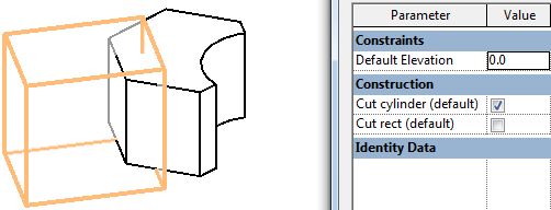
Void in Family Editor

Here is a workflow that demonstrates the confusing behaviour:

  • In the family editor, create a new Generic Model family
  • Tick the 'Cuts with Void When loaded' family property
  • Create a solid with two more intersecting solids
  • Change the two outside solids to voids 
  • The voids will not cut the solid - this is a deliberate technique to carefully control what cuts what
  • Use the 'Cut' command to cut one of the voids from the solid (only one)
  • Select the visible void and link its 'Cut Geometry' property to a parameter - say "Cut Rect"
  • Select the invisible void (that is cutting the solid)
  • link its 'Cut Geometry' property to another parameter - say "Cut Cylinder"
  • In theory, this should allow you to turn off 'cutting capability' of each void independently, once in the project - and hence whether they cut or not.

Test this in the Family Editor

  • With both voids 'cuttable', the cylinder cuts but the rectangular void does not (as expected) - this is because the rectangular void was never told to cut the solid, so it has no effect in the family


  • Turn off the 'cutting capability' of the cylinder - it no longer cuts the solid;  it actually becomes visible, which may seem contradictory - but that is typical Revit behaviour (voids not cutting anything show orange;  voids already cutting a solid disappear)

Switch the cutting properties around so the cylinder can cut but the rectangular cannot - visually it looks the same as having both properties ticked.


 Voids in the Project

From my earlier blog post on Cut with Void When Loaded in Revit, we know that in order for it to work in a project, the cutting void must be set to not actually cut anything in the family - as the rectangular void is set up.
 
  • Load the family into a project

  • Place the family onto an element that it intersect with
  • Both 'Cut Geometry' checkboxes ticked

  • Untick both checkboxes, so the cylinder void is no longer cutting the family solid (rectangular void does not cut it regardless)
  • Both voids are ghosted when the family is selected, or in pre-selection

  • Use the project 'Cut geometry' command with the host element and family
  • Both voids will cut the host element (neither void is cutting the family solid)


  • Tick the 'Cut Rect' checkbox -
    • The cylinder is not cutting the family solid, so it cuts the host element in the project (this may not be what you want, but it cannot be avoided!)
    • the rectangular void is not cutting the family void, so it cuts the host


  • Tick both boxes - only the rectangular void cuts the host (as it is not cutting the family solid)
    • The cylinder now cuts the family solid but not the host (and is no longer visibly ghosted)

Conclusion

  • If the void cuts a solid in the family, it cannot cut an element in the project using the 'Cuts with Void When loaded' family property
  • If the void cuts a solid in the family,the new (in v2021) 'Cut Geometry' property has the potential to work in a project
  • If the void does not cut a solid in the family, it can cut an element in the project using the 'Cuts with Void When loaded' family property - but only when you use the 'Cut' command in the project
  • If the void does not cut a solid in the family,the new (in v2021) 'Cut Geometry' property has absolutely no effect in the project

This probably makes sense if you think really hard about decisions the programmers had to make about what is possible and how it might work.

However, it is mighty confusing for the end user.

To make matters worse, we now have two entirely different 'Cut Geometry' functions in Revit:

  • 'Cut Geometry' property in the family - a checkbox
  • 'Cut Geometry' command:
    • in the family- where you actively select which elements cut each other
    • in the project - where you actively select which family cuts which element but the results depend on all kinds of things in the family (as described above).

All clear now?  Or still confused?


Sunday, 29 October 2017

New in Revit 2018.2 - Pattern Dialog Box


Following on from my last post about new features in Revit 2018.2, there are some very nice tweaks to the Pattern dialog boxes:

Fill Patterns

  • The Fill Pattern dialog box is now fully resizable (height & width) - Revit remembers the resize operation during the session.
  • The Fill Pattern dialog box has been redesigned to replace text icons with visual icons - as per many other Revit dialog boxes.
Revit 2018.2 dialog box
 
Old dialog box

  • No Pattern <None> is now at the top of the list (when accessed from a dialog box that has the option to remove a pattern, such as the Material dialog box) - this replaces the 'No Pattern' button at bottom left of the old dialog box.
  • Solid Fill is now second from the top of the list (Drafting patterns) after 'No Pattern' - generally I think this is a good thing.  NB. This is not the case with the Override dialog boxes, which have not yet been redesigned - so we have another new inconsistency.

  • There is now a Search/Filter function for patterns - it will filter the list to only include whatever contains the text you type into the 'Search' box.  It is not case sensitive.    Watch out for this feature:  if you have any text in the search/filter box, you may not see the <None> or Solid fill items at the top - it will take some getting used to, and will surely catch you out a few times.
  • It is now possible to select multiple fill patterns when the dialog box was accessed from the Manage toolbar (but not from dialogs that require you to choose a fill pattern to be used somewhere - like the material dialog box);  If multiple fill patterns are selected, they can be deleted but not edited (the edit icon is greyed out).

Edit Fill Patterns

The Edit Fill Pattern dialog box has been redesigned - the new overall layout is more logical:
Revit 2018.2 Edit Pattern dialog box
Old Edit Pattern dialog box

  • 'Simple' patterns are now labelled as 'Basic' 

  • When listing custom patterns from a pattern file, it shows 4 instead of 3.  When the dialog box is resized vertically, it only increases the size of the preview, not the list of custom patterns, so you still need to use the tiny scroll bar on the right.
  • The 'Import' button (on the left) has been replaced by a 'Browse' button (on the right) - why?
  • The Import Scale value has been unlocked so it can be changed at any time after importing - this sounds great but BIM Managers may not be happy as they will lose the ability to set and lock down pattern scales.
  • Changing the scale without re-importing is immensely useful, as we often do not know where the pattern came from.  In this situation,  the preview updates as soon as you change the scale.
  • We have lost the File Units -  Aaaargh!  Why?  I like to know if the source was metric or imperial.
  • As with the old dialog box, we cannot see the name of the imported pattern file, which would be useful.
  • We now have a search/filter function for custom patterns, which operates much like the one on the Fill Pattern dialog box - this only works immediately after importing a pattern file. 
  • The title 'Settings' seems a bit odd when the pattern is set to custom - it was obviously designed for Basic/simple patterns, where it is more appropriate.

Overall, this is a welcome change to the UI, with only a few minor quibbles.  It would be great to have many, many more such minor improvements that incrementally take away the pain of using Revit.