BILT Speaker

BILT Speaker
RevitCat - Revit Consultant
Showing posts with label drafting. Show all posts

Wednesday, 27 November 2019

Weird Reference Callout Rules in Revit

Over many years of struggling with Revit's numerous quirks, I have never quite figured out what the hidden rules are for Callouts.  Here are my latest thoughts after some detailed research:

Reference Callouts


When you tick the box 'Reference Other View' you get a list of possible views to reference.  That list of views is not predictable (so I thought) - however, I've narrowed down some extra rules about which views might be available:
  • A plan, section, elevation or detail view will only show in the list if it is cropped  (This caught me out at first).
  • A drafting view cannot be cropped - so the above rule does not apply.
  • A so-called "Rendering" view, which is actually like a drafting view with an image on it- so it cannot be cropped
  • Certain view family/types are available depending on the active view being placed in - see the list below.
  • If you apply the first two rules to the list of view types below, you might just be able to predict what can be referenced when.


Rules for 'Reference Other View' Callouts:

In a floor plan view, you can reference callout to:
  • Any drafting view
  • A detail Plan view (but not a section detail view)
  • A floor plan view (including Area plan and RCP)
  • A Rendering view


In a detail plan view, you can reference callout to:
  • Any drafting view
  • Any detail view (Plan or section)
  • Any section or elevation view
  • Not to any floor plan - (this is a big limitation)
  • A Rendering view

In a section view or section detail view, you can reference callout to:
  • Any drafting view
  • Any detail view (Plan or section)
  • Any other section or elevation view (But not to a floor plan)
  • A Rendering view
 
In a drafting view (or a rendering view), you can reference callout to:
  • Any drafting view
  • Any detail view
  • Any floor plan view (including Area plan and RCP)
  • Any other section or elevation view
  • A Rendering view


However, the choice of view type is not always that simple . . . .

In a previous post (about stair path arrows) I described the relative benefits of making your plan callouts 'Plan Views' vs 'Detail Views'.

You may also want to display your stairs differently in plan (compared to the standard 2D representation in plan views):
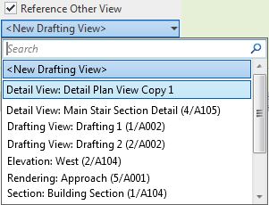
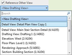
Weirder and Weirder

For more details on Callout weirdness, refer to:

Sunday, 17 February 2019

Stretcher Bond Hatching in Revit

A few years back I posted a description of how to create a complex custom hatch pattern for Revit - that example was for repeating octagons.  Since then I have often needed to quickly create much simpler patterns such as stretcher bond elevation views for bricks, blocks and tiles.  The Octagon pattern was quite complex and it still takes a while to get your head around the logic - so here is a much easier to follow set of examples:


Pattern Definition Format

The pattern file is a text file, saved with a '.pat' extension.
Definition of units (important for metric):
;%UNITS=MM

Each pattern definition has an * prefixed header :   a title and description separated by a comma
      *Stretcher 400x200,   400mm x 200mm stretcher bond
Drafting or Model definition:
       ;%TYPE=MODEL
Each line repeat (in the pattern) is described in one row of text, with comma delimited format.  eg:
0,     1200, 1000,         0,  1000,       400,  -1500

  • Angle  = angle of line from horizontal measured in an anti-clockwise direction
  • Origin x = horizontal distance of start of line from setout point (always orthogonal)
  • Origin y = vertical distance of start of line from setout point (always orthogonal)
  • Shift u (x axis of line) = offset distance of start of repeat line measured parallel to start of line
    (in the direction of the line,  ie. to match the angle).  The Shift values are measured from the start of the line, not from the setout point.
  • Shift v (y axis of line) = offset distance of start of repeat line measured perpendicular to start of line
  • Pen down = length of solid line measured in the direction of the line (optional - it draws a continuous line if omitted)
  • Pen up = length of gap in the line before the next segment of the line starts repeating (measured in the direction of the line);  is always a minus value.  (optional - as per pen down)
NB. I have labelled the shift directions as u & v (not x & y, as Autodesk labels them) because the directions relate to the axis of the line, not the whole pattern - so a vertical line would have a u offset measured vertically (labelled as x direction by Autodesk, which is confusing).

Stretcher Bond Hatching Definitions


A typical staggered tile pattern (stretcher bond) consists of :
  • a series of continuous horizontal lines at regular spacing;
  • Short vertical lines that run between alternate horizontal lines, at a spacing equal to the length of the brick/block/tile
  • Another set of short vertical lines that run between alternate horizontal lines, at a spacing equal to the length of the brick/block/tile - but these are typically offset horizontally by half a length and vertically by one pattern height.
These should almost always be defined as MODEL patterns, as they are meant to be dimensionally correct on the surface of the material.

There are actually two ways to define this:

Option 1 - separate definitions for the two vertical lines

*Stretcher-450x150-1/2,      450 x 150 1/2 stretcher bond
;%TYPE=MODEL
0,         0,0,           0,150
90,       0,0,           0,450,        150,-150
90,    225,150,      0,450,        150,-150

The first row defines the horizontal lines
0,         0,0,           0,150
  • The lines are at zero degrees (horizontal)
  • The first line starts at 0 offset from the origin, both x and y (0,0)
  •  The repeat has a shift of zero horizontally (x or u), and 150mm vertically (y or v) from the line origin (0,150),
  • The next repeat is the same values (0,150) from the start of the previous repeat. 
  • The line is continuous, as the are no pen up/down values


The second row defines the first set of vertical lines
90,       0,0,           0,450,        150,-150
  • The lines are at 90 degrees (vertical )
  • The first line starts at 0 offset from the origin, both x and y (0,0)
  •  The repeat has a shift of zero vertically (u) , and 450mm horizontally (v) , from the line origin (0,450)
  • The next repeat is the same values (0,450) from the start of the previous repeat. 
  • The line is segmented, 150mm solid, 150mm gap (pen up/down 150,-150)
The v shift in this instance is horizontal, perpendicular to the line, with a positive value to the left of the line origin (same as pattern setout point in this case). 
  • As the pattern is symmetrical, it makes no difference if the v shift value is positive or negative
  • Seen below in context, the pattern repeats in both directions from the origin:


The third row defines the second set of vertical lines
90,    225,150,      0,450,        150,-150
  • The lines are at 90 degrees (vertical )
  • The first line starts at 225mm x offset from the origin, and 150mm y offset from the origin (225,150) - ie. half a tile along and one tile up.
  • The repeat has a shift of zero vertically (u) , and 450mm horizontally (v) , from the line origin (0,450)
  • The next repeat is the same values (0,450) from the start of the previous repeat. 
  • The line is segmented, 150mm solid, 150mm gap (pen up/down 150,-150)


Option 2 - one definition for both vertical lines

*Stretcher-450x150-1/2,      450 x 150 1/2 stretcher bond
;%TYPE=MODEL
0,         0,0,           0,150
90,       0,0,       150,225,        150,-150


The first row defines the horizontal lines as per previous method
0,         0,0,           0,150

The second row defines the vertical lines
90,       0,0,       150,225,        150,-150
  • The lines are at 90 degrees (vertical )
  • The first line starts at 0 offset from the origin, both x and y (0,0)
  •  The repeat has a shift of 150mm vertically (u) , and 225mm horizontally (v) , from the line origin (150,225)
  • The next repeat is the same values (150,225) from the start of the previous repeat. 
  • The line is segmented, 150mm solid, 150mm gap (pen up/down 150,-150)


  • As the pattern is symmetrical, it makes no difference if the u and v shift values are positive or negative
  • Seen below in context, the pattern repeats in both directions from the origin:


One Third Shift Patterns

The same principles can be applied when the bond is staggered by differing proportions.


Option 1 - separate definitions for each vertical line


*Stretcher-450x150-1/3,   450 x 150 1/3 stretcher bond
;%TYPE=MODEL
0,          0,0,         0,150
90,        0,0,         0,450,       150,-300 
90,    150,150,     0,450,       150,-300
90,    300,300,     0,450,       150,-300


 90,    150,150,     0,450,       150,-300

  • 90 degrees
  • 150mm x line origin, 150mm y line origin
  • Zero u shift repeat, 450mm v shift repeat
  • 150mm Pen Down, 300mm gap (Pen Up)


 90,    300,300,     0,450,       150,-300
  • 90 degrees
  • 300mm x line origin, 300mm y line origin
  • Zero u shift repeat, 450mm v shift repeat
  • 150mm Pen Down, 300mm gap (Pen Up)

Option 2 - one definitions for all vertical lines

*Stretcher-450x150-1/2,      450 x 150 1/2 stretcher bond
;%TYPE=MODEL
0,         0,0,           0,150
90,       0,0,       150,300,        150,-300
Horizontal shift (v) repeat has to be 2/3 of a tile (300mm)

As the joint offset is not half a tile, the same result can be achieved with a negative v shift repeat of -150mm:
0,         0,0,           0,150
90,       0,0,       150,-150,        150,-300


An offset by one third to the left could be achieved by a positive 150mm v shift:
0,         0,0,           0,150
90,       0,0,       150,150,        150,-300


Two Third Shift Patterns

Some patterns cannot have their vertical lines defined by only one row, as you can't define a consistent diagonal repeat.  Therefore you must have multiple rows for the vertical lines.

*Staggered-450x150-2/3, 450 x 150 2/3 stretcher bond
;%TYPE=MODEL
0,          0,0,        0,150
90,        0,0,        0,450,     150,-150
90,    300,150,    0,450,     150,-150


The direction of stagger can be changed with the x origin value:

*Staggered-450x150+2/3, 450 x 150 2/3 stretcher bond
;%TYPE=MODEL
0,          0,0,        0,150
90,        0,0,        0,450,     150,-150
90,    150,150,    0,450,     150,-150

Flemish Bond

More complex brick patterns require extra rows of definition:


*Flemish-240x86,     240 x 86 (Australian Brick size) Flemish stretcher bond
;%TYPE=MODEL
0,           0,0,         0,86
90,         0,0,         0,360,       86,-86 
90,      240,0,        0,360,       86,-86
90,        60,86,      0,360,       86,-86
90,      180,86,      0,360,       86,-86


You could continue this theme with increasing random looking patterns, but I'll leave that for you to figure out . . . . . .


Sunday, 29 October 2017

New in Revit 2018.2 - Pattern Dialog Box


Following on from my last post about new features in Revit 2018.2, there are some very nice tweaks to the Pattern dialog boxes:

Fill Patterns

  • The Fill Pattern dialog box is now fully resizable (height & width) - Revit remembers the resize operation during the session.
  • The Fill Pattern dialog box has been redesigned to replace text icons with visual icons - as per many other Revit dialog boxes.
Revit 2018.2 dialog box
 
Old dialog box

  • No Pattern <None> is now at the top of the list (when accessed from a dialog box that has the option to remove a pattern, such as the Material dialog box) - this replaces the 'No Pattern' button at bottom left of the old dialog box.
  • Solid Fill is now second from the top of the list (Drafting patterns) after 'No Pattern' - generally I think this is a good thing.  NB. This is not the case with the Override dialog boxes, which have not yet been redesigned - so we have another new inconsistency.

  • There is now a Search/Filter function for patterns - it will filter the list to only include whatever contains the text you type into the 'Search' box.  It is not case sensitive.    Watch out for this feature:  if you have any text in the search/filter box, you may not see the <None> or Solid fill items at the top - it will take some getting used to, and will surely catch you out a few times.
  • It is now possible to select multiple fill patterns when the dialog box was accessed from the Manage toolbar (but not from dialogs that require you to choose a fill pattern to be used somewhere - like the material dialog box);  If multiple fill patterns are selected, they can be deleted but not edited (the edit icon is greyed out).

Edit Fill Patterns

The Edit Fill Pattern dialog box has been redesigned - the new overall layout is more logical:
Revit 2018.2 Edit Pattern dialog box
Old Edit Pattern dialog box

  • 'Simple' patterns are now labelled as 'Basic' 

  • When listing custom patterns from a pattern file, it shows 4 instead of 3.  When the dialog box is resized vertically, it only increases the size of the preview, not the list of custom patterns, so you still need to use the tiny scroll bar on the right.
  • The 'Import' button (on the left) has been replaced by a 'Browse' button (on the right) - why?
  • The Import Scale value has been unlocked so it can be changed at any time after importing - this sounds great but BIM Managers may not be happy as they will lose the ability to set and lock down pattern scales.
  • Changing the scale without re-importing is immensely useful, as we often do not know where the pattern came from.  In this situation,  the preview updates as soon as you change the scale.
  • We have lost the File Units -  Aaaargh!  Why?  I like to know if the source was metric or imperial.
  • As with the old dialog box, we cannot see the name of the imported pattern file, which would be useful.
  • We now have a search/filter function for custom patterns, which operates much like the one on the Fill Pattern dialog box - this only works immediately after importing a pattern file. 
  • The title 'Settings' seems a bit odd when the pattern is set to custom - it was obviously designed for Basic/simple patterns, where it is more appropriate.

Overall, this is a welcome change to the UI, with only a few minor quibbles.  It would be great to have many, many more such minor improvements that incrementally take away the pain of using Revit.

Saturday, 19 March 2016

Copying Sheets Between Revit Projects

A year ago I published a post about copying views between Revit projects.  This has recently been receiving a lot of hits, so it is obviously a big issue for Revit users.  Here is another tip related to this topic, with credit due to Alex Dobysh of Mirvac in Sydney, who showed the concept to me:

Copying Sheets

You might think it is not possible to copy and paste sheets between projects.  Well, normally it is not, but there are certain situations where it is possible - kind of . . .

In the project browser, if you right-click on a sheet, the option to 'Copy to Clipboard' is normally greyed out

However, if the sheet does not have any model views on it, then 'Copy to Clipboard' is enabled

In this situation, Revit considers Legend views to be model views even if they do not have any components placed on them.  It is curious why it does this, since legends can be placed on multiple sheets - yet another of Revit's legendary inconsistencies (pardon the pun).

Once you have copied a sheet to the clipboard, you can go to another project in the same Revit session, and 'Paste from Clipboard'
This will create a new sheet with exactly the same layout of title block, schedule views and any annotation (text etc);  it brings with it the schedules in the same location and format as the original sheet;  it also brings drafting views - but if those already exist with the same name, it creates a new drafting view with a number suffix.  As schedules are allowed on multiple sheets, it does not create new ones if those already exist.

You can also paste sheets within the same project to create copies of them - it just increments the sheet number and puts a number suffix to the sheet name.  If there are any drafting views on the sheet, it will duplicate them and increment a number suffix.  This is a quick way to create multiple similar sheets - all you need to do after that is add the model views

Links for Copying Views

Copying views between Revit projects
Copying contents of 3D views between Projects
Duplicating Views with Linework Overrides (within projects)

Sunday, 8 March 2015

Copying Views Between Revit Projects

I figured out how to copy perspective views between Revit projects a few years back.  I see that this topic has been addressed in various blogs and forum posts, but maybe not comprehensively, so I reckon its worth putting it all in one place for reference.

There are several methods to copy views, depending on what view type and where you are in the project browser.
  • Copying a view between projects is quite different from using the 'Duplicate' command because that command only works within a project.
  • Selecting a view in the project browser does not generally allow you to copy it - the copy icon is not available, nor is there a 'Copy' option when you right-click on a view name (Drafting views and schedules are the exception).
  • Copying views between projects does not usually copy associated annotation objects, with the exception of drafting views.  Annotation has to be selected and copied separately after the view is copied.
  • None of the following methods will work between different Revit sessions - however, I see no reason why anyone should open more than one Revit session anyway.

Copying Drafting Views & Schedules

Drafting and schedule views can be copied from one project to another by two methods:
Method A - Copy & Paste
  • Select a drafting view or schedule in the project browser
  • Right-click and choose 'Copy to Clipboard'
 
  • Go to the other project
  • 'Paste' from Clipboard

  • Regardless of where the focus is (Project Browser or canvas), it will paste the view into the other project

Method B
You only need to open the project to be copied into, and use the 'Insert from File' command
  • Then select the project that you want to copy views from - it will list allowable view types, and even preview them.
  • It will also allow you to copy sheets that have only drafting or schedule views on those sheets.
  • As soon as sheets have other view types on them (including legends), it will not even list them in the Insert Views dialog box
 Method C
  • If a drafting view that you have copied by method A or B contains callouts to other drafting views, they will be copied across into your project, even if they are not on the sheet (in the case of inserted sheets) - and the callouts will link correctly.  
  • NB. this does not occur when drafting view callouts are contained on other views types that are copied (sections, detail or plan views etc).
  • If you try to copy a plan or section by selecting its view crop boundary, you can also select a drafting view callout on that view - it will also be copied to clipboard.  However, when you paste the view, it will bring along the callout but disassociate it from the drafting view (which it does not copy across).

Copying 3D Views (isometric or perspective)

Copy Method 1.
If you have a 3D view open, you can select the view crop boundary, then right-click and copy or else use the copy to clipboard icon from the ribbon.
 
Copy Method 2.
If you have another view open, you can find the view name (to be copied) in the project browser, then right-click on it and select 'Show Camera'
It will show the camera definition of the selected 3D view (be it isometric or perspective)
 
Then you can copy to clipboard

Paste Method 1
If you are in a plan view in another project, all you need to do is 'Paste Aligned to Current View' and the identical 3D view definition will be created in the same location.
Paste Method 2
  • If you are in a 3D view in another project, when you try to paste the 3D view it will not give you the option to paste to the current location.  
  • You have to paste to a Selected level (choose the appropriate one);  
  • if you try to 'Paste from Clipboard' you will not be able to get the view into exactly the same location as it was in the first project - so that is not recommended.

Copying Plan Views

You can use the same method (1) for copying plan views between projects:
  1. Select the view crop boundary of the plan view, 
  2. copy to clipboard
  3. Go to the other project
  4. Paste - Aligned to Current View or to Selected Level
  • If you paste to Current View, it will create a new plan view associated to the same level as the current view;  if the original associated level name exists in the new project it may be named 'Temp.Level 1' regardless of the associated level or the original name;  if you paste again, it will create a new plan view named 'Temp.Level 2' 
  • If you paste to Selected Level, it will create a new view associated to that level - again named 'Temp.Level 1' (or the next number in sequence), not the actual level number.
  • It will not copy associated annotation from the original view, unless you select those at the same time as the view crop boundary
  • It will copy most view properties of the original view, but not an associated View Template, even if that same view template exists in both projects.

Copying Section Views

You can copy a section view easily by selecting the section marker in plan (or the section view crop boundary in the section view itself)
  • When you paste the section into another project you need to remember to go to the same level it was copied from before pasting to Current View (or Selected Level) otherwise the heights will be different.
  • Section view properties will be copied, with the exception of assigned view templates.

Copying Elevation Views

You can copy an elevation view either by selecting the elevation marker or the individual elevation itself;  if you copy the whole marker it will include associated elevation views
 

Copying Area Plan Views

You can copy Area Plans by selecting their view crop boundary.
  • When you paste them, they may retain the view name - if the associated level from the view in the original project does not exist in the new project; otherwise it will rename to a temp view name.
  • You can paste them to multiple selected levels, in which case the views are renamed with a number suffix, which do not relate to the levels that they become associated with - so you need to rename them

Copying Detail Views & Callouts

  • You can select a callout from a plan, section or elevation view, then Copy to Clipboard
  • Alternatively you can select the view crop boundary and right-click to copy it
  • You can then go to the recipient project and paste Aligned to Current View or to Selected Views or Same Place (but not to Selected Levels)

  • The detail view will be created and a callout placed on the view that you selected;  if a detail view of that name already exists it will rename the new one with the next number suffix.

Copying Legend Views

I have not found a way to copy legend views between projects - legend views do not allow view crop boundaries.  So, what you need to do is to create a new legend view in the project, then copy and paste all the annotation objects from the original legend view in the other project.

Make sure that your new legend view is the same scale as the original, otherwise text and symbol size will appear to change.

Copying View Templates

View templates have to be copied by a totally different method:
  • Open both the projects that you want to copy from (donor) and to (recipient)
  • In the recipient project, go to 'Manage' 'Transfer Project Standards'
  • Click on 'Check None' to deselect all items in the list
  • Select View Templates
  • Click OK to proceed - it will copy all view templates from the donor project into your active project - you have no choice in the matter.
  • NB. If you want to copy only a few view templates, you could create a new intermediate project;  import all view templates into that; remove the ones you don't want from the intermediate project; then transfer the remaining ones from the intermediate project into the recipient project.
  • When you copy views from one project to another, it copies most view properties, but not assigned view templates.  In that situation, you would need to transfer the view templates separately (as described above), then manually reassign to each copied view.

More on Copying Sheets and Views

Refer to this link to find out how to copy sheets between projects
Also Copying contents of 3D views between Projects
and  Duplicating Views with Linework Overrides (within projects)

Please add a comment if you know more or better ways to copy views between projects.