BILT Speaker

BILT Speaker
RevitCat - Revit Consultant
Showing posts with label spacing. Show all posts

Friday, 27 March 2020

Revit Tags Label Extents and Leaders

One of the things that always annoys me in Revit is the hardcoded spacing or sizes of certain elements or settings.  These include such things as:
  • Default extension of grid lines and levels beyond a cropped view on a sheet - this appears to be just over one inch on the sheet (I was expecting it to be exactly one inch = 25.4mm).
    Why oh why does it have to be so big - all that wasted paper on plots;  or wasted time adjusting each one manually.

  •  Tag Leader Offsets - it seems the leaders go to the opposite extreme, being really tight in to the text.  If your boss does not like that graphic, you are in trouble.


Text Leader Offsets

A few years back, Autodesk actually solved a similar issue for text in Revit - although with text, prior to that the leaders had a locked in 2.032mm offset, which was equally irritating.

In Revit version 2011, Autodesk added the parameter "Leader/Border Offset", which gave us the ability to control how far the leader started from the text (even when no border was applied to the text).

Default text leader offset = 2.032mm
  • If you want the leader closer in, just change the offset to 0.5mm or 0mm

Zero mm text leader offset
 
  • If you want the leader further away, change the offset to something larger

Text leader offset 3.5mm
  • You can also add a border, which matches the leader offset exactly


The default offset in all the Autodesk templates is still 2.032mm, which is way too big.  Likewise in all projects that were upgraded in v2011, it set the value to 2.032mm.

I wonder how many BIM Managers around the world actually went in and set the value to a sensible number?  I like it to be say 0.5mm, but some people like 0mm.

Tag Leader Offsets

Sadly, Autodesk never finished that task (now where have you heard that before?).

Text labels inside tags do not follow these rules – leader offset makes no difference unless the tag-label has a border enabled.
Without a border, the leader just uses the extents of the tag family, and it considers tag-text with no border to have an offset of zero regardless of what it is set to.

For some reason the vertical and horizontal offsets are not consistent. If the leader is pointing up or down the offset is visually acceptable, but when it is left or right it is just a bit too small an offset, and looks wrong. 

  • With no border and a large leader offset the leader is tight in to the text label
Tag label leader 3.5mm no border

  •  With a small leader offset the leader is still tight in to the text label
Tag label leader offset 0mm no border
  •  The tag looks exactly the same (no leader offset)
Tag label leader 3.5mm no border


  •  As soon as you add a border, the leader offset matches that border (as per text)
Tag label leader 3.5mm


This is yet another little inconsistency in Revit to irritate you. 

Does anyone know a way to address this?

Nasty Workaround

I hate to suggest this, but if your job depends on it you could try adding a border to the tag label and make it white, so it does not show on a plot/pdf (in label Type properties).  Interestingly, the text remains black.


But we all know what kind of trouble that might cause later on . . .


Sunday, 17 February 2019

Stretcher Bond Hatching in Revit

A few years back I posted a description of how to create a complex custom hatch pattern for Revit - that example was for repeating octagons.  Since then I have often needed to quickly create much simpler patterns such as stretcher bond elevation views for bricks, blocks and tiles.  The Octagon pattern was quite complex and it still takes a while to get your head around the logic - so here is a much easier to follow set of examples:


Pattern Definition Format

The pattern file is a text file, saved with a '.pat' extension.
Definition of units (important for metric):
;%UNITS=MM

Each pattern definition has an * prefixed header :   a title and description separated by a comma
      *Stretcher 400x200,   400mm x 200mm stretcher bond
Drafting or Model definition:
       ;%TYPE=MODEL
Each line repeat (in the pattern) is described in one row of text, with comma delimited format.  eg:
0,     1200, 1000,         0,  1000,       400,  -1500

  • Angle  = angle of line from horizontal measured in an anti-clockwise direction
  • Origin x = horizontal distance of start of line from setout point (always orthogonal)
  • Origin y = vertical distance of start of line from setout point (always orthogonal)
  • Shift u (x axis of line) = offset distance of start of repeat line measured parallel to start of line
    (in the direction of the line,  ie. to match the angle).  The Shift values are measured from the start of the line, not from the setout point.
  • Shift v (y axis of line) = offset distance of start of repeat line measured perpendicular to start of line
  • Pen down = length of solid line measured in the direction of the line (optional - it draws a continuous line if omitted)
  • Pen up = length of gap in the line before the next segment of the line starts repeating (measured in the direction of the line);  is always a minus value.  (optional - as per pen down)
NB. I have labelled the shift directions as u & v (not x & y, as Autodesk labels them) because the directions relate to the axis of the line, not the whole pattern - so a vertical line would have a u offset measured vertically (labelled as x direction by Autodesk, which is confusing).

Stretcher Bond Hatching Definitions


A typical staggered tile pattern (stretcher bond) consists of :
  • a series of continuous horizontal lines at regular spacing;
  • Short vertical lines that run between alternate horizontal lines, at a spacing equal to the length of the brick/block/tile
  • Another set of short vertical lines that run between alternate horizontal lines, at a spacing equal to the length of the brick/block/tile - but these are typically offset horizontally by half a length and vertically by one pattern height.
These should almost always be defined as MODEL patterns, as they are meant to be dimensionally correct on the surface of the material.

There are actually two ways to define this:

Option 1 - separate definitions for the two vertical lines

*Stretcher-450x150-1/2,      450 x 150 1/2 stretcher bond
;%TYPE=MODEL
0,         0,0,           0,150
90,       0,0,           0,450,        150,-150
90,    225,150,      0,450,        150,-150

The first row defines the horizontal lines
0,         0,0,           0,150
  • The lines are at zero degrees (horizontal)
  • The first line starts at 0 offset from the origin, both x and y (0,0)
  •  The repeat has a shift of zero horizontally (x or u), and 150mm vertically (y or v) from the line origin (0,150),
  • The next repeat is the same values (0,150) from the start of the previous repeat. 
  • The line is continuous, as the are no pen up/down values


The second row defines the first set of vertical lines
90,       0,0,           0,450,        150,-150
  • The lines are at 90 degrees (vertical )
  • The first line starts at 0 offset from the origin, both x and y (0,0)
  •  The repeat has a shift of zero vertically (u) , and 450mm horizontally (v) , from the line origin (0,450)
  • The next repeat is the same values (0,450) from the start of the previous repeat. 
  • The line is segmented, 150mm solid, 150mm gap (pen up/down 150,-150)
The v shift in this instance is horizontal, perpendicular to the line, with a positive value to the left of the line origin (same as pattern setout point in this case). 
  • As the pattern is symmetrical, it makes no difference if the v shift value is positive or negative
  • Seen below in context, the pattern repeats in both directions from the origin:


The third row defines the second set of vertical lines
90,    225,150,      0,450,        150,-150
  • The lines are at 90 degrees (vertical )
  • The first line starts at 225mm x offset from the origin, and 150mm y offset from the origin (225,150) - ie. half a tile along and one tile up.
  • The repeat has a shift of zero vertically (u) , and 450mm horizontally (v) , from the line origin (0,450)
  • The next repeat is the same values (0,450) from the start of the previous repeat. 
  • The line is segmented, 150mm solid, 150mm gap (pen up/down 150,-150)


Option 2 - one definition for both vertical lines

*Stretcher-450x150-1/2,      450 x 150 1/2 stretcher bond
;%TYPE=MODEL
0,         0,0,           0,150
90,       0,0,       150,225,        150,-150


The first row defines the horizontal lines as per previous method
0,         0,0,           0,150

The second row defines the vertical lines
90,       0,0,       150,225,        150,-150
  • The lines are at 90 degrees (vertical )
  • The first line starts at 0 offset from the origin, both x and y (0,0)
  •  The repeat has a shift of 150mm vertically (u) , and 225mm horizontally (v) , from the line origin (150,225)
  • The next repeat is the same values (150,225) from the start of the previous repeat. 
  • The line is segmented, 150mm solid, 150mm gap (pen up/down 150,-150)


  • As the pattern is symmetrical, it makes no difference if the u and v shift values are positive or negative
  • Seen below in context, the pattern repeats in both directions from the origin:


One Third Shift Patterns

The same principles can be applied when the bond is staggered by differing proportions.


Option 1 - separate definitions for each vertical line


*Stretcher-450x150-1/3,   450 x 150 1/3 stretcher bond
;%TYPE=MODEL
0,          0,0,         0,150
90,        0,0,         0,450,       150,-300 
90,    150,150,     0,450,       150,-300
90,    300,300,     0,450,       150,-300


 90,    150,150,     0,450,       150,-300

  • 90 degrees
  • 150mm x line origin, 150mm y line origin
  • Zero u shift repeat, 450mm v shift repeat
  • 150mm Pen Down, 300mm gap (Pen Up)


 90,    300,300,     0,450,       150,-300
  • 90 degrees
  • 300mm x line origin, 300mm y line origin
  • Zero u shift repeat, 450mm v shift repeat
  • 150mm Pen Down, 300mm gap (Pen Up)

Option 2 - one definitions for all vertical lines

*Stretcher-450x150-1/2,      450 x 150 1/2 stretcher bond
;%TYPE=MODEL
0,         0,0,           0,150
90,       0,0,       150,300,        150,-300
Horizontal shift (v) repeat has to be 2/3 of a tile (300mm)

As the joint offset is not half a tile, the same result can be achieved with a negative v shift repeat of -150mm:
0,         0,0,           0,150
90,       0,0,       150,-150,        150,-300


An offset by one third to the left could be achieved by a positive 150mm v shift:
0,         0,0,           0,150
90,       0,0,       150,150,        150,-300


Two Third Shift Patterns

Some patterns cannot have their vertical lines defined by only one row, as you can't define a consistent diagonal repeat.  Therefore you must have multiple rows for the vertical lines.

*Staggered-450x150-2/3, 450 x 150 2/3 stretcher bond
;%TYPE=MODEL
0,          0,0,        0,150
90,        0,0,        0,450,     150,-150
90,    300,150,    0,450,     150,-150


The direction of stagger can be changed with the x origin value:

*Staggered-450x150+2/3, 450 x 150 2/3 stretcher bond
;%TYPE=MODEL
0,          0,0,        0,150
90,        0,0,        0,450,     150,-150
90,    150,150,    0,450,     150,-150

Flemish Bond

More complex brick patterns require extra rows of definition:


*Flemish-240x86,     240 x 86 (Australian Brick size) Flemish stretcher bond
;%TYPE=MODEL
0,           0,0,         0,86
90,         0,0,         0,360,       86,-86 
90,      240,0,        0,360,       86,-86
90,        60,86,      0,360,       86,-86
90,      180,86,      0,360,       86,-86


You could continue this theme with increasing random looking patterns, but I'll leave that for you to figure out . . . . . .


Monday, 2 October 2017

Weird Railing Stuff - part 8 - Moving Handrail Supports

I have explained previously that Revit handrail support spacing is measured along the length of  sloping handrails, not horizontal (plan) distance.

What does this mean when it comes to moving individual supports on a handrail?  Well, the rules are equally weird, but differently weird.

In the following  example, you might want the spacing to be measured horizontally (in plan), so you need to move the supports on the sloping parts of the handrail.

The first thing to do is select just the support (Tab, select), and unpin it.  This will allow you to slide the support along handrail - but most likely you want to be very precise about how far it is moved.  You might try using the 'Align' tool, providing you have something like a reference plane to align to:

Law of Diminishing Returns


In this context, the Align tool does not do what you expect - it presents you with more Revit Weirdness.  Once you select the reference plane to align to, then click on the support centreline, it moves the support only about two-thirds of the way (this fraction probably varies depending on the slope of the railing). 


My first thought was that it was converting the horizontal distance to an actual distance up the slope of the handrail - but it is not that value (something slightly different).  It is using some other mysterious mathematical rule that I cannot fathom.

If you try Align again, it goes another two-thirds of the remaining distance.

 Try again and you get closer - but you will never quite get there.  There has to be a better way?

Move Weirdness

If you try using the 'Move' command, and select a horizontal distance, you get exactly the same result as the Align tool - it does not move it to where you tell it.  The same 'Law of diminishing returns' applies.

The Move (Workaround) Solution

The trick here is to use the move command, but make sure that you snap to the end point of the support, and then have a reference line that has an end (or intersection) point exactly where you want it to be placed - slightly above the underside of the handrail.

The Slide (Workaround) Solution

There is another trick - providing you have a (reference) line running vertically and stopping exactly where you want it to be placed (as with the previous workaround), you can just select it and slide it along the handrail, and it will snap to the right place.  However, I do not recommend this because if your reference line is too long or short, it may look like it went to the right spot but could be slightly off.  The move command is more precise.

Reset Warning

If you click on the 'Reset Rail' or 'Reset Railing' commands, you will lose all of those careful support relocations on the whole handrail - each moved support would be moved back and repinned, while deleted supports would be reinstated (including those silly ones exactly on the ends of handrails).


More on this subject:

Wednesday, 27 September 2017

Weird Railing Stuff - part 7a - Support Spacing Postscript

I mentioned in my previous post about handrail support spacing that the distance between supports is measured along the length of the handrail regardless of its angle, rather than a horizontal plan distance (which is used by other railing element spacing).  It turns out that it gets even weirder:

Revit Railings Get Weirder and Weirder

I thought I would check where it is measured on the handrail, and whether it takes into account a fillet radius if you have one.
  • On a horizontal railing, it measures support spacing on the underside of the handrail
  • On a sloping railing, the supports seem to be attached to the handrail a bit higher - you can snap to the top endpoint of the support.  In the example I tested, with a 75mm high support, the top is about 7mm vertically into the handrail.
  • This means that the spacing is measured slightly above the underside of a sloping handrail - this may vary depending on the angle and the type of support.  However, I have no desire to investigate any further - this is weird enough already.
  • If you have a curved transition from horizontal to sloping handrail (fillet radius), the support spacing measurement transitions (on a radius) from underside of handrail to somewhere above the underside.
  • This means that you cannot accurately predict where the supports will end up - unless you do a checking diagram like the one below.  I can tell you, this is the first and last one I will ever do!

 Extension to Floor

I know that you'd never put supports like this on a handrail with a vertical extension to the floor, but I just wanted to see what it does with the spacing:

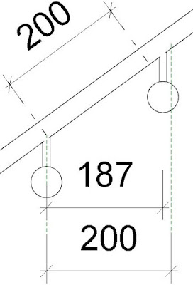
The answer is that the supports get flipped to the outside of the handrail (what becomes the top when it turns the corner to be horizontal).  However, the spacing between the two supports as it goes from vertical to horizontal is not predictable.  In the example above, the typical spacing is 200mm (just to be certain it doesn't come away from the wall!), but the distance measured orthogonally between those two supports on the corner is only about 190mm - so we are adrift by 10mm.  As I said, it is not easy to predict exactly where the supports will end up.

If we had a start/end indent property, we could at least make a guess, then tweak the indent value until it is exactly where we want the first/last support - without having to unpin the supports (which has its own problems, to be discussed later).  Please go to the official Revit Ideas website and vote up my idea on this

Just to entertain you, here is what Revit does when you have a handrail extension to a wall - note that the support goes to the top of the handrail again (not that you actually want a support when the handrail fixes to a wall, of course!).

More on this subject:

Sunday, 24 September 2017

Weird Railing Stuff - part 7 - Support Spacing

It amazes me that very few Reviteers make use of the 'Railing Support' capability that we have had in the software for over 5 years now.  In fact, a very large percentage of users don't even know they exist
Here are some possible reasons why that is the case:
  • If you upgrade a project with the old style railings in it, they are not converted to the new style railings, so you cannot use railing supports in them.  To achieve this, you have to copy a new railing type into your project, then swap the old family type to a new one to get access to the support functionality.
  • The metric project templates provided by Autodesk do not include any railings that use handrail supports (this includes the Australian and UK templates);  they do have some support families - but if you don't know how to use them, you'll never figure it out by playing around with the railing samples.
  • The sample files that you can download from the Autodesk Knowledge website include only the old method of using balusters to look like handrail supports - and that is the imperial unit sample file, which you would expect to be the most likely one to be updated when the software was changed (The metric version would have no chance, even if you could find it on the Autodesk labyrinth-site).  I wonder if anyone at Autodesk knows what QA means?  'Quality Assurance' is the correct answer, not 'Quick As (get this out the door)'.
  • The settings for adding supports are buried deep as type properties of a nested family.  The chances of finding this are slim - although that has improved recently with the ability to get to a handrail family properties directly from the railing type properties dialog box with one mouse click.
  • The methodology for setting up handrail supports is mind-bogglingly complicated and counter-intuitive - and it is all type-based properties hidden inside handrail families nested into the railing family.
  • Even when you have set up the supports in a handrail family, you have to remember to choose left or right (for the handrail) in the railing family, otherwise nothing shows up.

Handrail Support Spacing

Once you have figured out how to set up Handrail Supports in a railing,you will obviously want to control the spacing - first the initial spacing, and then changing the spacing.  There are at least two weird things you need to know about this - the first is how illogical and inconsistent the spacing properties are.  The second weird thing relates to moving the supports - to be dealt with later:

Spacing Properties

Do you think it is weird that baluster spacing and handrail/top rail extension length properties are measured in plan distance regardless of the slope of the railings, while support spacing is measured along the actual length of the handrail whether it is horizontal, sloping, vertical or going round a twirly flourish at the end?  Whichever one is correct, it is weirdly inconsistent.

How would you measure the support distances on this handrail?
In the Handrail type properties, you have the typical Revit options (plus a special one):
  • None
  • Fixed Distance
  • Align With Posts
  • Fixed Number
  • Maximum Spacing
  • Minimum Spacing
Unfortunately these are not consistent with each other, and none of them will give you the outcome that you desire (unless by a fluke the spacing just happens to work for your stair):

1.  'Fixed Number' does not put supports at the ends of the railing;  the spacing varies depending on the overall railing length, and the number that you put in - NB. the number is a type property of the handrail, which means that you most likely need a unique handrail type and a unique railing type for every single instance of the railing.
It seems that the supports always use centre justification for this - it is greyed out and you can't change it;  also, the greyed out value for spacing is just a remembered value from the previous settings, and is misleading here.  Revit does not report back to you what the actual support spacing is on each handrail instance.

If you have a free end handrail, you would typically want a support close to the end (but not exactly at the end).  You don't get a support anywhere near the end, unless you put in a ridiculous number of supports, like 50 in this example.
Fixed number does not put supports at the ends
If you have an extension to wall or floor, then this option makes sense, however, the spacing includes the length of the extension, measured along the handrail, including vertical length for a floor extension.  The example below, with a wall extension is the one and only situation where Revit gets the support locations close to what you might need, albeit that you need a separate type for each different number of supports.


2.  'Fixed Distance' only puts a support at the start or end of the handrail if the justification is set to Beginning or End;  the distance at the other end is pot-luck depending on the overall handrail length.  If the justification is 'Center', then the distance from the start and end again depends totally on the overall length of the handrail - so it is luck of the draw, but it will be the same at each end.
The calculated distance includes extensions.


 3.  'Maximum Spacing' always puts a support exactly at the start and end of the handrail; justification is not an option here - it is greyed out (and set to center).  Just imagine sending this drawing to a builder or fabricator - you'd be laughed off the site.

Revit does not take into account whether an extension with a wall or floor fixing is chosen - it still puts a support in place at the very end, just where it is fixed to the wall/floor.

4.  'Minimum Spacing' behaves just like the Maximum Spacing settings, although the actual spacing will be different.

5.  'Align with Posts' is an interesting option - I don't get why you would use it, unless your posts are non-supporting in themselves.  If you do use it, you have no option for supports between the posts, so what good is that?  I would have thought the option should be 'Align with Posts & Maximum Spacing Between' and suchlike.  Or 'Maximum Spacing Except at Posts' etc.

With all of these options, you have the opportunity to unpin a support and move or delete it; [Edit - thanks to Peter Schiettecatte for pointing this out:] but you can only add additional supports by unpinning an existing one and copying it along the handrail (a clever but not too obvious workflow).  However, once you have done this, it takes just one innocent (or stupid) click on the 'Reset Railings' button to lose all that hard-won support over-ride spacing.

The Solution

What we really need to solve some of these issues is to have consistency in how the spacing is applied (at ends); and the ability to set start and end indent properties for handrail support spacing.  These would operate rather like the equivalent properties on a 'Divided Path', although I guess they'd need to be type properties to be consistent with all the other handrail properties (Oh, how I wish most of those were instance properties in the actual railing)

If you think this is a good idea, please go to the official Revit Ideas website and vote up my idea on this.

 More on this subject