BILT Speaker

BILT Speaker
RevitCat - Revit Consultant
Showing posts with label elevation. Show all posts

Monday, 25 May 2020

Weird Callout Behaviour in Revit

A few months back I wrote about some of the weird rules for Revit Callouts when you use the 'Reference Other View' option.

There are some strange and frustrating restrictions, which mean you need to plan carefully about what view types/families to use for callouts, and in fact for any views.

There are also some weird restrictions in how Callouts work when you don't use 'Reference Other View' - I refer to those as "Real Callouts".  I am going to record those here.

Stop and Think - Which Parent View?

Before placing any "Real Callouts",  stop and think about which view you want to place the callout on - you should already have a good plan for how your drawing set referencing is going to work.

The reason for this is that once you place a Real Callout on a view, it does two things:
  • It creates a new view that is automatically cropped to the extents of the callout that you just created.
  • It places the callout element on your view - typically a dashed line rectangle with a circular reference bubble.
It is  really important to know that once you place a Real Callout on a particular view, it can never be moved to another parent view.

The only workarounds are:
  • Start from scratch - delete the callout + view, which means losing all your annotation and any other reference callouts to that view.
  • Hide the callout on the parent view, and make a Reference Callout on another parent view.  This means that the old parent view can never be deleted - you would lose the callout view (refer to Deleting Callouts below). 
    This is a last resort workaround that I would not recommend.

Callout View Families

Detail Views vs Plan Views

The first issue to watch out for when creating Real Callouts is which view type you select (or don't select if you just accept the default).  For plan callouts you have two family options (and then choices of any view types that you have created):
  • Detail Views
  • Floor Plan Views

The really important thing to know here is that once you have made a decision between Detail or Floor Plan family, you can never change your mind - the families are not interchangeable.

View types are changeable - so you can change a callout from one plan view type to another plan view (but not to a Detail view).

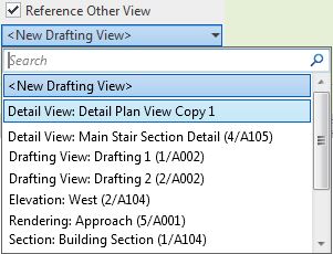
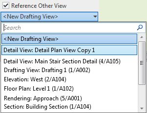
Once you have chosen a callout view family/type, there are many weird and inconsistent rules about which view families can be referenced to and from callouts - refer to weird rules for Revit Callouts for 'Reference Other View'

For those and other reasons, I normally try to avoid using Detail views at all in Revit - see more reasons below, and refer to Weird Stair Path Stuff.

Detail Views vs Section Views

When creating Section view Callouts you also have two family options (and then choices of any view types that you have created):
  • Detail Views
  • Section Views
Unlike plan details, section details can be changed to normal section views - this is inconsistent, although it is welcome not to have that restriction.


Weird Detail View Behaviour

Detail views behave quite differently to other view types:
  • Plan and Section views are typically grouped together in the project browser - it does not distinguish between them.  This can be confusing when searching for views.
  • Detail views can be rotated in section (or elevation) from a vertical (section) orientation to a plan orientation.  If you know what you are doing you can use this to your advantage - but is not advised for inexperienced users.  It will most likely cause much confusion.
  • When creating Real Callouts from a Detail view, they can only be another detail view.
  • Stairs and railings are displayed as cut 3D models (wherever the view cutting plane is), rather than the Revit conventional 2D representation on other plan views - refer to True 3D Stair View in RCP.
  • Symbols nested into families (such as electical fittings - switches, power outlets) are not visible in Detail views.
  • Section and Plan Detail Callouts have the ability to set the depth of view the same as the parent view or independently - however, the controls are by 'Far Clip Offset' for both section and plan, not by view range.


Plan Detail Views

Plan Detail views have special rules (different to Section Details):
For Plan Detail views, the callouts are generally only visible in the views they are placed on, with one exception:
  • There is a ‘Show In’ property that can override this behaviour
  • Plan callout views are normally set to Show In ‘Parent View Only’ 
  • If this is changed to ‘Intersecting Views’ then the callout can potentially be visible in other plans within the same view range (thus behaving more like section detail callouts) - be warned, this will confuse the heck out of most Revit users.
  • Be aware that ‘Intersecting Views’ detail plan callouts can also be visible in sections – they may appear as a line or with a reference head depending on the properties of the plan view


Section Detail Views

Section Detail callout views are potentially visible in section views other than their parent view.  They behave as if they have a hard-coded 'Show in Intersecting Views' property.  They might be visible under the following conditions:
  • The callout view crop boundary is wholly within the crop boundary of the other section view
  • The callout view section line is within the Clipping Distance of the other section view
  • There are no other scale-related, category visibility or filters hiding them. 

Duplicating Views

  • If you copy and paste a real callout, it actually creates a new view (and new callout).  In most cases this is not especially useful, as you are more likely to want the same reference to the original callout view - in which case it would need to be a 'Reference Other View' callout.
  • If you copy a parent view by ‘Duplicate with Detailing’ it creates a new view for each callout – each would have a different reference on the duplicatd parent view. 


Deleting Views

  • If you delete a parent view (plan or section), it will automatically delete any callouts placed on that view, and the callout views - although it does prompt you with a warning that it will delete those views.
  • There is no way around this because once a callout is placed on a particular view, it cannot be moved to another parent view.
  • This is a major drawback to using callouts in Revit.

Next Time . . .

In addition to the issues above, there is a limitation on not being able to have a callout rectangle that is slightly larger than the crop region of the callout view - thus making your drawings messy and hard to read.  Refer to Callout crop boundary mismatch


In the next blog post on this subject I will suggest an alternative working method that avoids some of these pitfalls and inconsistencies.


If you can remember all these rules and exceptions, congratulations!  Try remembering them again in a few months time.

Wednesday, 27 November 2019

Weird Reference Callout Rules in Revit

Over many years of struggling with Revit's numerous quirks, I have never quite figured out what the hidden rules are for Callouts.  Here are my latest thoughts after some detailed research:

Reference Callouts


When you tick the box 'Reference Other View' you get a list of possible views to reference.  That list of views is not predictable (so I thought) - however, I've narrowed down some extra rules about which views might be available:
  • A plan, section, elevation or detail view will only show in the list if it is cropped  (This caught me out at first).
  • A drafting view cannot be cropped - so the above rule does not apply.
  • A so-called "Rendering" view, which is actually like a drafting view with an image on it- so it cannot be cropped
  • Certain view family/types are available depending on the active view being placed in - see the list below.
  • If you apply the first two rules to the list of view types below, you might just be able to predict what can be referenced when.


Rules for 'Reference Other View' Callouts:

In a floor plan view, you can reference callout to:
  • Any drafting view
  • A detail Plan view (but not a section detail view)
  • A floor plan view (including Area plan and RCP)
  • A Rendering view


In a detail plan view, you can reference callout to:
  • Any drafting view
  • Any detail view (Plan or section)
  • Any section or elevation view
  • Not to any floor plan - (this is a big limitation)
  • A Rendering view

In a section view or section detail view, you can reference callout to:
  • Any drafting view
  • Any detail view (Plan or section)
  • Any other section or elevation view (But not to a floor plan)
  • A Rendering view
 
In a drafting view (or a rendering view), you can reference callout to:
  • Any drafting view
  • Any detail view
  • Any floor plan view (including Area plan and RCP)
  • Any other section or elevation view
  • A Rendering view


However, the choice of view type is not always that simple . . . .

In a previous post (about stair path arrows) I described the relative benefits of making your plan callouts 'Plan Views' vs 'Detail Views'.

You may also want to display your stairs differently in plan (compared to the standard 2D representation in plan views):

Weirder and Weirder

For more details on Callout weirdness, refer to:

Sunday, 17 February 2019

Stretcher Bond Hatching in Revit

A few years back I posted a description of how to create a complex custom hatch pattern for Revit - that example was for repeating octagons.  Since then I have often needed to quickly create much simpler patterns such as stretcher bond elevation views for bricks, blocks and tiles.  The Octagon pattern was quite complex and it still takes a while to get your head around the logic - so here is a much easier to follow set of examples:


Pattern Definition Format

The pattern file is a text file, saved with a '.pat' extension.
Definition of units (important for metric):
;%UNITS=MM

Each pattern definition has an * prefixed header :   a title and description separated by a comma
      *Stretcher 400x200,   400mm x 200mm stretcher bond
Drafting or Model definition:
       ;%TYPE=MODEL
Each line repeat (in the pattern) is described in one row of text, with comma delimited format.  eg:
0,     1200, 1000,         0,  1000,       400,  -1500

  • Angle  = angle of line from horizontal measured in an anti-clockwise direction
  • Origin x = horizontal distance of start of line from setout point (always orthogonal)
  • Origin y = vertical distance of start of line from setout point (always orthogonal)
  • Shift u (x axis of line) = offset distance of start of repeat line measured parallel to start of line
    (in the direction of the line,  ie. to match the angle).  The Shift values are measured from the start of the line, not from the setout point.
  • Shift v (y axis of line) = offset distance of start of repeat line measured perpendicular to start of line
  • Pen down = length of solid line measured in the direction of the line (optional - it draws a continuous line if omitted)
  • Pen up = length of gap in the line before the next segment of the line starts repeating (measured in the direction of the line);  is always a minus value.  (optional - as per pen down)
NB. I have labelled the shift directions as u & v (not x & y, as Autodesk labels them) because the directions relate to the axis of the line, not the whole pattern - so a vertical line would have a u offset measured vertically (labelled as x direction by Autodesk, which is confusing).

Stretcher Bond Hatching Definitions


A typical staggered tile pattern (stretcher bond) consists of :
  • a series of continuous horizontal lines at regular spacing;
  • Short vertical lines that run between alternate horizontal lines, at a spacing equal to the length of the brick/block/tile
  • Another set of short vertical lines that run between alternate horizontal lines, at a spacing equal to the length of the brick/block/tile - but these are typically offset horizontally by half a length and vertically by one pattern height.
These should almost always be defined as MODEL patterns, as they are meant to be dimensionally correct on the surface of the material.

There are actually two ways to define this:

Option 1 - separate definitions for the two vertical lines

*Stretcher-450x150-1/2,      450 x 150 1/2 stretcher bond
;%TYPE=MODEL
0,         0,0,           0,150
90,       0,0,           0,450,        150,-150
90,    225,150,      0,450,        150,-150

The first row defines the horizontal lines
0,         0,0,           0,150
  • The lines are at zero degrees (horizontal)
  • The first line starts at 0 offset from the origin, both x and y (0,0)
  •  The repeat has a shift of zero horizontally (x or u), and 150mm vertically (y or v) from the line origin (0,150),
  • The next repeat is the same values (0,150) from the start of the previous repeat. 
  • The line is continuous, as the are no pen up/down values


The second row defines the first set of vertical lines
90,       0,0,           0,450,        150,-150
  • The lines are at 90 degrees (vertical )
  • The first line starts at 0 offset from the origin, both x and y (0,0)
  •  The repeat has a shift of zero vertically (u) , and 450mm horizontally (v) , from the line origin (0,450)
  • The next repeat is the same values (0,450) from the start of the previous repeat. 
  • The line is segmented, 150mm solid, 150mm gap (pen up/down 150,-150)
The v shift in this instance is horizontal, perpendicular to the line, with a positive value to the left of the line origin (same as pattern setout point in this case). 
  • As the pattern is symmetrical, it makes no difference if the v shift value is positive or negative
  • Seen below in context, the pattern repeats in both directions from the origin:


The third row defines the second set of vertical lines
90,    225,150,      0,450,        150,-150
  • The lines are at 90 degrees (vertical )
  • The first line starts at 225mm x offset from the origin, and 150mm y offset from the origin (225,150) - ie. half a tile along and one tile up.
  • The repeat has a shift of zero vertically (u) , and 450mm horizontally (v) , from the line origin (0,450)
  • The next repeat is the same values (0,450) from the start of the previous repeat. 
  • The line is segmented, 150mm solid, 150mm gap (pen up/down 150,-150)


Option 2 - one definition for both vertical lines

*Stretcher-450x150-1/2,      450 x 150 1/2 stretcher bond
;%TYPE=MODEL
0,         0,0,           0,150
90,       0,0,       150,225,        150,-150


The first row defines the horizontal lines as per previous method
0,         0,0,           0,150

The second row defines the vertical lines
90,       0,0,       150,225,        150,-150
  • The lines are at 90 degrees (vertical )
  • The first line starts at 0 offset from the origin, both x and y (0,0)
  •  The repeat has a shift of 150mm vertically (u) , and 225mm horizontally (v) , from the line origin (150,225)
  • The next repeat is the same values (150,225) from the start of the previous repeat. 
  • The line is segmented, 150mm solid, 150mm gap (pen up/down 150,-150)


  • As the pattern is symmetrical, it makes no difference if the u and v shift values are positive or negative
  • Seen below in context, the pattern repeats in both directions from the origin:


One Third Shift Patterns

The same principles can be applied when the bond is staggered by differing proportions.


Option 1 - separate definitions for each vertical line


*Stretcher-450x150-1/3,   450 x 150 1/3 stretcher bond
;%TYPE=MODEL
0,          0,0,         0,150
90,        0,0,         0,450,       150,-300 
90,    150,150,     0,450,       150,-300
90,    300,300,     0,450,       150,-300


 90,    150,150,     0,450,       150,-300

  • 90 degrees
  • 150mm x line origin, 150mm y line origin
  • Zero u shift repeat, 450mm v shift repeat
  • 150mm Pen Down, 300mm gap (Pen Up)


 90,    300,300,     0,450,       150,-300
  • 90 degrees
  • 300mm x line origin, 300mm y line origin
  • Zero u shift repeat, 450mm v shift repeat
  • 150mm Pen Down, 300mm gap (Pen Up)

Option 2 - one definitions for all vertical lines

*Stretcher-450x150-1/2,      450 x 150 1/2 stretcher bond
;%TYPE=MODEL
0,         0,0,           0,150
90,       0,0,       150,300,        150,-300
Horizontal shift (v) repeat has to be 2/3 of a tile (300mm)

As the joint offset is not half a tile, the same result can be achieved with a negative v shift repeat of -150mm:
0,         0,0,           0,150
90,       0,0,       150,-150,        150,-300


An offset by one third to the left could be achieved by a positive 150mm v shift:
0,         0,0,           0,150
90,       0,0,       150,150,        150,-300


Two Third Shift Patterns

Some patterns cannot have their vertical lines defined by only one row, as you can't define a consistent diagonal repeat.  Therefore you must have multiple rows for the vertical lines.

*Staggered-450x150-2/3, 450 x 150 2/3 stretcher bond
;%TYPE=MODEL
0,          0,0,        0,150
90,        0,0,        0,450,     150,-150
90,    300,150,    0,450,     150,-150


The direction of stagger can be changed with the x origin value:

*Staggered-450x150+2/3, 450 x 150 2/3 stretcher bond
;%TYPE=MODEL
0,          0,0,        0,150
90,        0,0,        0,450,     150,-150
90,    150,150,    0,450,     150,-150

Flemish Bond

More complex brick patterns require extra rows of definition:


*Flemish-240x86,     240 x 86 (Australian Brick size) Flemish stretcher bond
;%TYPE=MODEL
0,           0,0,         0,86
90,         0,0,         0,360,       86,-86 
90,      240,0,        0,360,       86,-86
90,        60,86,      0,360,       86,-86
90,      180,86,      0,360,       86,-86


You could continue this theme with increasing random looking patterns, but I'll leave that for you to figure out . . . . . .


Wednesday, 15 June 2016

Revit 2017 Elevation Depth Cueing Pt 2

A few weeks back I reviewed the new Revit 2017 feature of Elevation Depth Cueing.
I have since realised that I may not have been entirely fair in how I portrayed this feature, particularly in regard to line weights . . .

The whole concept of applying different line weights according to distance from the cut plane is not as simple as you might think.  If Revit tried to apply thinner lines in the distance, how would it handle angled walls?  Or curved walls?  Should the line thicknesses taper as the angled/curved wall receded in the distance?  That could be pretty tricky to achieve, and the rules would be very hard to decide, let alone implement.  Or would you like an angled wall to start off one thickness close up to you, then step to a thinner line weight further back, and then step again - certainly not, that would look terrible.

So, on reflection, perhaps Autodesk chose the right option, which was to fade the lines instead of messing with line thicknesses?  It certainly is a simpler solution, which follows obvious rules and it does so more or less as you'd expect - with the exception of not applying to anything modified by the Linework tool, which I would prefer it to do.

Angled Walls

Here is a sample elevation of an angled wall - it handles the gradation very well.  Just imagine how it might look with changing line weights.

The same goes for a curved wall:
 

Conclusion

This may not be the tool that you expected, because it does not follow traditional drafting conventions of using line weights to convey distance.  However, it does very neatly handle all kinds of situations and view types (hidden line, shaded, realistic, shadows etc).  The controls over how it manages and defines the changes in distance may be very simplistic, but they are simple to understand once you look at the help file diagrams.

If we wanted a more complex solution, it would have been a lot more complicated to use, and I suspect we might still be waiting.

Click here for comments on other Revit 2017 features.