BILT Speaker

BILT Speaker
RevitCat - Revit Consultant
Showing posts with label model. Show all posts

Wednesday, 24 November 2021

Revit Mirror Command is So Not BIM

 What is one of the first things that you teach people who are moving from Autocad to Revit?

"When making changes in Revit, DO NOT delete and replace elements - you should always modify the original elements even if it takes longer" 

Why is that?  Because you never know what data or hosted elements are attached to existing elements - so if you "Delete and Replace" you might lose the data or hosted elements.

  • What does the middle initial of BIM stand for?  "Information".
  • Without "Information" you are just working with a 3D Building Model

Revit Mirror Command

Revit is a BIM program, Right?

So you would imagine that it's fundamental command structure would work towards maintaining the BIM concept?

Unfortunately the "Mirror" Command in Revit doesn't follow the BIM rules.

It does not just mirror the selected element(s) - it copies and deletes original, even when Copy is unticked.

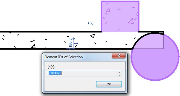
  • Select an element
  • Check it's Element ID

  • Mirror the element (with "Copy" unticked)
  • Check the Element ID of the mirrored element
  • Aargh, it is different

So what?  Well, it is just not BIM !


What does this Mean for your model?

Cut elements are no longer cut when mirrored

Joined elements are no longer joined when mirrored

etc

To test this:

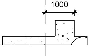
  • Create a new family that has "Cut with Voids When Loaded" enabled:

  • Place a solid and void in the family (not intersecting each other)

  • Load the family into a project
  • Place a component where it intersects with another element (in this example, a wall of the same material)
  • Join the component and the other element (wall)
  • Cut the component and the other element (wall)
  • Mirror the component (No copy)
  • Component is no longer joined or cut

Compare to other Revit Commands

  • Undo the mirror command
  • Test the Move and Rotate commands (no copy)
  • Join and Cut are maintained


These commands are BIM compliant - original elements are manipulated

Hosted Elements are Deleted by Mirror Command

  • Add a dimension (or tag) to the component
  • Mirror (no copy) the component
  • If you are lucky you might get a warning about the impending loss of the hosted dimension


What to Do?  Is there a Workaround?

The first thing to do is to contact Autodesk and request that they fix this un-BIM-like behaviour

Despite this problem having existed for over 20 years, it will surely be fixed promptly for you if you ask nicely.

In the meantime . . . . .

There is another way to mirror components in Revit:


Control the Mirror Command

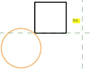
Families can have their own built-in mirror/flip controls.

In the family editor, place a "Control"


  • Reload the family
  • Select the component
  • Check its Element ID


  • Click on the Mirror control
  • The component will flip around its origin point
  • Check the Element ID
  • Woohoo - it is the same! 
  • And the Join and Cut are maintained


Flipping Hosts

Test the flipping control with a hosted element (dimension)

  •  It is not guaranteed to maintain the dimension, but you have a much better chance

Conclusion

Is this going to help you?

Maybe:

  • Obviously it only allows you to flip components one by one.
  • As the flip controls will mirror about the component origin, it may not end up exactly where you need it - but you can then move it

  • It will try to maintain any cutting and joining that you have done
  • It may warn you that joined elements no longer intersect - and you should have the option to unjoin or maintain the join (if the elements will later intersect again)
  • I have not tested the implications for Dynamo - I have no idea if it is possible to access the flip controls within Dynamo.

Revit Ideas Wishlist

There are already a couple of ideas relating to this on the Autodesk Revit Ideas Wishlist

Mirror Not Copy (for mechanical elements but applies to all)

MirrorElement Not Copy API


Monday, 17 May 2021

Revit Family Error Automatically Resolved

Some of you may not be aware but Autodesk sneaked in a new "Feature/Enhancement" in about version 2018 (I think?) - I do not remember any discussion or announcement about this in the testing/release process:

Warning:  "Family Error Automatically Resolved"

When you try to place or modify a component using parameter values that break the family (eg. cause impossible geometry), Revit will now try to "Fix" the family.

In reality, what is most likely going to happen is that you (the BIM or Content Manager) will be in a "Fix" or "Fixed Up" . . . . .

So, what is going on here?  


 When Revit tries to "Fix" the family, it seems that :

  • Revit makes the requested change to the values
  • Gives a warning to the user
    • As we know, most users ignore the warning and keep going
    • User clicks on OK or presses Enter

  • Revit omits the elements that it cannot create
    • Nested components are particularly prone to this
  • This results in a component that is missing some (sub)elements
 
  • The end user may not know what has happened
    • They may not knotice that something is mssing
    • They may not care!
  • If the user makes further changes to the values that still break the family, Revit gives another warning - this one requires no user intervention.

  • If the user changes the values to something that no longer breaks the family, it appears to reinstate the elements that it could not create.  
    • When I first encountered this, I was sure that once it happened, Revit would never reinstate the missing elements - but on re-testing this it appears to work ok.


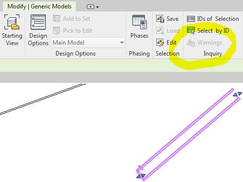
Warning

  • It seems that when Revit "Fixes" a family for you, it does NOT retain a warning in the list
  • I think that is a serious failing with this feature, as the BIM Manager has no easy way to find or track the problem

Old Revit Versions

Prior to this "enhancement", Revit would just give a message saying that it could not create the family:


This meant that the user had to either choose values that did not break the family, or else get the Content Creator to fix the family so it did not happen.


Opinions

What do you think of this "Enhancement"?

  • As a BIM, Model or Content Manager I don't think I like it much because it means I often don't get told about the error - so it goes uncorrected.
    • It is not easy to find later on
  • As a Revit User, you might think it is great as you can get on with my work and not be interrupted by having to seek help from the Content Creator
    • It may or may not come back to bite you - chances are that it will become someone else's problem.  
    • If it goes unnoticed for a while the ramifications of the problem could become more significant.


Sunday, 17 February 2019

Stretcher Bond Hatching in Revit

A few years back I posted a description of how to create a complex custom hatch pattern for Revit - that example was for repeating octagons.  Since then I have often needed to quickly create much simpler patterns such as stretcher bond elevation views for bricks, blocks and tiles.  The Octagon pattern was quite complex and it still takes a while to get your head around the logic - so here is a much easier to follow set of examples:


Pattern Definition Format

The pattern file is a text file, saved with a '.pat' extension.
Definition of units (important for metric):
;%UNITS=MM

Each pattern definition has an * prefixed header :   a title and description separated by a comma
      *Stretcher 400x200,   400mm x 200mm stretcher bond
Drafting or Model definition:
       ;%TYPE=MODEL
Each line repeat (in the pattern) is described in one row of text, with comma delimited format.  eg:
0,     1200, 1000,         0,  1000,       400,  -1500

  • Angle  = angle of line from horizontal measured in an anti-clockwise direction
  • Origin x = horizontal distance of start of line from setout point (always orthogonal)
  • Origin y = vertical distance of start of line from setout point (always orthogonal)
  • Shift u (x axis of line) = offset distance of start of repeat line measured parallel to start of line
    (in the direction of the line,  ie. to match the angle).  The Shift values are measured from the start of the line, not from the setout point.
  • Shift v (y axis of line) = offset distance of start of repeat line measured perpendicular to start of line
  • Pen down = length of solid line measured in the direction of the line (optional - it draws a continuous line if omitted)
  • Pen up = length of gap in the line before the next segment of the line starts repeating (measured in the direction of the line);  is always a minus value.  (optional - as per pen down)
NB. I have labelled the shift directions as u & v (not x & y, as Autodesk labels them) because the directions relate to the axis of the line, not the whole pattern - so a vertical line would have a u offset measured vertically (labelled as x direction by Autodesk, which is confusing).

Stretcher Bond Hatching Definitions


A typical staggered tile pattern (stretcher bond) consists of :
  • a series of continuous horizontal lines at regular spacing;
  • Short vertical lines that run between alternate horizontal lines, at a spacing equal to the length of the brick/block/tile
  • Another set of short vertical lines that run between alternate horizontal lines, at a spacing equal to the length of the brick/block/tile - but these are typically offset horizontally by half a length and vertically by one pattern height.
These should almost always be defined as MODEL patterns, as they are meant to be dimensionally correct on the surface of the material.

There are actually two ways to define this:

Option 1 - separate definitions for the two vertical lines

*Stretcher-450x150-1/2,      450 x 150 1/2 stretcher bond
;%TYPE=MODEL
0,         0,0,           0,150
90,       0,0,           0,450,        150,-150
90,    225,150,      0,450,        150,-150

The first row defines the horizontal lines
0,         0,0,           0,150
  • The lines are at zero degrees (horizontal)
  • The first line starts at 0 offset from the origin, both x and y (0,0)
  •  The repeat has a shift of zero horizontally (x or u), and 150mm vertically (y or v) from the line origin (0,150),
  • The next repeat is the same values (0,150) from the start of the previous repeat. 
  • The line is continuous, as the are no pen up/down values


The second row defines the first set of vertical lines
90,       0,0,           0,450,        150,-150
  • The lines are at 90 degrees (vertical )
  • The first line starts at 0 offset from the origin, both x and y (0,0)
  •  The repeat has a shift of zero vertically (u) , and 450mm horizontally (v) , from the line origin (0,450)
  • The next repeat is the same values (0,450) from the start of the previous repeat. 
  • The line is segmented, 150mm solid, 150mm gap (pen up/down 150,-150)
The v shift in this instance is horizontal, perpendicular to the line, with a positive value to the left of the line origin (same as pattern setout point in this case). 
  • As the pattern is symmetrical, it makes no difference if the v shift value is positive or negative
  • Seen below in context, the pattern repeats in both directions from the origin:


The third row defines the second set of vertical lines
90,    225,150,      0,450,        150,-150
  • The lines are at 90 degrees (vertical )
  • The first line starts at 225mm x offset from the origin, and 150mm y offset from the origin (225,150) - ie. half a tile along and one tile up.
  • The repeat has a shift of zero vertically (u) , and 450mm horizontally (v) , from the line origin (0,450)
  • The next repeat is the same values (0,450) from the start of the previous repeat. 
  • The line is segmented, 150mm solid, 150mm gap (pen up/down 150,-150)


Option 2 - one definition for both vertical lines

*Stretcher-450x150-1/2,      450 x 150 1/2 stretcher bond
;%TYPE=MODEL
0,         0,0,           0,150
90,       0,0,       150,225,        150,-150


The first row defines the horizontal lines as per previous method
0,         0,0,           0,150

The second row defines the vertical lines
90,       0,0,       150,225,        150,-150
  • The lines are at 90 degrees (vertical )
  • The first line starts at 0 offset from the origin, both x and y (0,0)
  •  The repeat has a shift of 150mm vertically (u) , and 225mm horizontally (v) , from the line origin (150,225)
  • The next repeat is the same values (150,225) from the start of the previous repeat. 
  • The line is segmented, 150mm solid, 150mm gap (pen up/down 150,-150)


  • As the pattern is symmetrical, it makes no difference if the u and v shift values are positive or negative
  • Seen below in context, the pattern repeats in both directions from the origin:


One Third Shift Patterns

The same principles can be applied when the bond is staggered by differing proportions.


Option 1 - separate definitions for each vertical line


*Stretcher-450x150-1/3,   450 x 150 1/3 stretcher bond
;%TYPE=MODEL
0,          0,0,         0,150
90,        0,0,         0,450,       150,-300 
90,    150,150,     0,450,       150,-300
90,    300,300,     0,450,       150,-300


 90,    150,150,     0,450,       150,-300

  • 90 degrees
  • 150mm x line origin, 150mm y line origin
  • Zero u shift repeat, 450mm v shift repeat
  • 150mm Pen Down, 300mm gap (Pen Up)


 90,    300,300,     0,450,       150,-300
  • 90 degrees
  • 300mm x line origin, 300mm y line origin
  • Zero u shift repeat, 450mm v shift repeat
  • 150mm Pen Down, 300mm gap (Pen Up)

Option 2 - one definitions for all vertical lines

*Stretcher-450x150-1/2,      450 x 150 1/2 stretcher bond
;%TYPE=MODEL
0,         0,0,           0,150
90,       0,0,       150,300,        150,-300
Horizontal shift (v) repeat has to be 2/3 of a tile (300mm)

As the joint offset is not half a tile, the same result can be achieved with a negative v shift repeat of -150mm:
0,         0,0,           0,150
90,       0,0,       150,-150,        150,-300


An offset by one third to the left could be achieved by a positive 150mm v shift:
0,         0,0,           0,150
90,       0,0,       150,150,        150,-300


Two Third Shift Patterns

Some patterns cannot have their vertical lines defined by only one row, as you can't define a consistent diagonal repeat.  Therefore you must have multiple rows for the vertical lines.

*Staggered-450x150-2/3, 450 x 150 2/3 stretcher bond
;%TYPE=MODEL
0,          0,0,        0,150
90,        0,0,        0,450,     150,-150
90,    300,150,    0,450,     150,-150


The direction of stagger can be changed with the x origin value:

*Staggered-450x150+2/3, 450 x 150 2/3 stretcher bond
;%TYPE=MODEL
0,          0,0,        0,150
90,        0,0,        0,450,     150,-150
90,    150,150,    0,450,     150,-150

Flemish Bond

More complex brick patterns require extra rows of definition:


*Flemish-240x86,     240 x 86 (Australian Brick size) Flemish stretcher bond
;%TYPE=MODEL
0,           0,0,         0,86
90,         0,0,         0,360,       86,-86 
90,      240,0,        0,360,       86,-86
90,        60,86,      0,360,       86,-86
90,      180,86,      0,360,       86,-86


You could continue this theme with increasing random looking patterns, but I'll leave that for you to figure out . . . . . .


Wednesday, 29 August 2018

Creating Swept Blends in Revit Mass - CME Part 5

Part 5 of my series on  comparing the five traditional form creation tools with equivalent techniques in the Revit Conceptual Massing Environment.
Previously we analysed the creation of extrusion forms, Blends, Revolves, and Sweeps in the CME.  Next up is Swept Blends:

Part 5:  Swept Blends

Creating a Swept Blend in the Conceptual Massing Environment. . . .

  • A swept blend requires two or more profiles, each perpendicular to the path ;
  • In the traditional Revit environment, a swept blend can only have two profiles;
  • Unlike a sweep, the path can only consist of one element (line, arc or curve), even if the profiles are closed;
  • Unlike a sweep, the profile cannot contain a loop within a loop (to make a hollow form);
  • The easiest way to do this is to host the profiles on points – in the example here, an arc has 3 points that define it, so they can also be used to host the profiles


  • The profiles can be model lines, reference lines or loaded 2D profile components - each method has its own advantages or disadvantages (described below) depending on how you want to modify the form later on, so there is no clear 'best method';
  • Create Form by selecting the profiles and the path
  • In this example, the profiles are the same shape, so there is a smooth transition, and you cannot even see the middle profile
  • NB. If you had just selected the profiles, Revit would decide its own path, which may not match the one you created – in which case the form would become a ‘Lofted’ shape

Edit Form

Editing behaviour differs, depending on the original profiles and path:

  • For model line profiles, you can use ‘Edit Profile’ – it will prompt you for which profile to edit, so you may need to put the form into X-Ray mode to be able to select the middle profile(s) or use wire-frame mode
  • In sketch mode you can modify the profile, or change it entirely
  • However, if you don't have the same number and type of segments in each profile, it may result in sharp edges
  • Try matching the segments in each profile, to make the transitions smooth, without edges  

  • For reference line profiles, the profiles can only be changed in size/proportion, depending on how much you can manipulate the reference lines without breaking the profile (but you cannot add segments)
  • For loaded component profiles, they can be parametrically controlled (best method), but you cannot reload a profile with a different configuration or number of segments 

 Point Hosting

  • The Autodesk help files recommend putting the profile(s) onto points hosted on the path (rather than using the points that define the path in the example above) – this has several advantages: it should give more control with moving end points and rotation


  • Unlike a sweep, when you create a form, it does not extend along the whole path – only between the first and last profile


If you adjust the path underneath, the form follows it:


If the profiles were model lines, then the lines and host points on the path are ‘consumed’, which means the host points cannot be selected or manipulated, and the model lines have limited controllability (except in edit profile sketch mode).

Dissolve


If the form is dissolved the model lines and points are kind of reinstated but not to exactly their original state:
  • Circles are split into semi-circles
  • Points lose their display status
For this reason, you may need to recreate or rehost the profiles after dissolving a form, and reset some properties.


Loft vs Swept Blend

The important thing to note with Swept Blends is that the path is included during the creation of the form, but does not become part of the form itself;  when the path is modified, the form changes too.
If the path is not included, the form becomes a 'Loft'. 

The inclusion of the path can be extremely useful when it comes to modifying the form - as will be seen later . . .

Youtube

For more info on this, view the Youtube video:
Create a swept blend in Revit CME