BILT Speaker

BILT Speaker
RevitCat - Revit Consultant
Showing posts with label command. Show all posts

Wednesday, 24 November 2021

Revit Mirror Command is So Not BIM

 What is one of the first things that you teach people who are moving from Autocad to Revit?

"When making changes in Revit, DO NOT delete and replace elements - you should always modify the original elements even if it takes longer" 

Why is that?  Because you never know what data or hosted elements are attached to existing elements - so if you "Delete and Replace" you might lose the data or hosted elements.

  • What does the middle initial of BIM stand for?  "Information".
  • Without "Information" you are just working with a 3D Building Model

Revit Mirror Command

Revit is a BIM program, Right?

So you would imagine that it's fundamental command structure would work towards maintaining the BIM concept?

Unfortunately the "Mirror" Command in Revit doesn't follow the BIM rules.

It does not just mirror the selected element(s) - it copies and deletes original, even when Copy is unticked.

  • Select an element
  • Check it's Element ID

  • Mirror the element (with "Copy" unticked)
  • Check the Element ID of the mirrored element
  • Aargh, it is different

So what?  Well, it is just not BIM !


What does this Mean for your model?

Cut elements are no longer cut when mirrored

Joined elements are no longer joined when mirrored

etc

To test this:

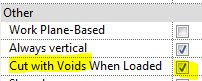
  • Create a new family that has "Cut with Voids When Loaded" enabled:
  • Place a solid and void in the family (not intersecting each other)

  • Load the family into a project
  • Place a component where it intersects with another element (in this example, a wall of the same material)
  • Join the component and the other element (wall)
  • Cut the component and the other element (wall)
  • Mirror the component (No copy)
  • Component is no longer joined or cut

Compare to other Revit Commands

  • Undo the mirror command
  • Test the Move and Rotate commands (no copy)
  • Join and Cut are maintained


These commands are BIM compliant - original elements are manipulated

Hosted Elements are Deleted by Mirror Command

  • Add a dimension (or tag) to the component
  • Mirror (no copy) the component
  • If you are lucky you might get a warning about the impending loss of the hosted dimension


What to Do?  Is there a Workaround?

The first thing to do is to contact Autodesk and request that they fix this un-BIM-like behaviour

Despite this problem having existed for over 20 years, it will surely be fixed promptly for you if you ask nicely.

In the meantime . . . . .

There is another way to mirror components in Revit:


Control the Mirror Command

Families can have their own built-in mirror/flip controls.

In the family editor, place a "Control"


  • Reload the family
  • Select the component
  • Check its Element ID


  • Click on the Mirror control
  • The component will flip around its origin point
  • Check the Element ID
  • Woohoo - it is the same! 
  • And the Join and Cut are maintained


Flipping Hosts

Test the flipping control with a hosted element (dimension)

  •  It is not guaranteed to maintain the dimension, but you have a much better chance

Conclusion

Is this going to help you?

Maybe:

  • Obviously it only allows you to flip components one by one.
  • As the flip controls will mirror about the component origin, it may not end up exactly where you need it - but you can then move it

  • It will try to maintain any cutting and joining that you have done
  • It may warn you that joined elements no longer intersect - and you should have the option to unjoin or maintain the join (if the elements will later intersect again)
  • I have not tested the implications for Dynamo - I have no idea if it is possible to access the flip controls within Dynamo.

Revit Ideas Wishlist

There are already a couple of ideas relating to this on the Autodesk Revit Ideas Wishlist

Mirror Not Copy (for mechanical elements but applies to all)

MirrorElement Not Copy API


Monday, 3 February 2020

Room Bounding Structural Column Materials in Revit


I recently discovered yet another obscure, hidden away setting in Revit - when I was investigating the "Room Bounding" property of different elements.

It seems that some structural columns have a "Room Bounding" property - but not all.
This has to be one of the weirdest, arbitrary decisions made by the Revit programmers:

Material for Model Behaviour

Structural columns have a weird property - so obscure and arcane, not to mention hidden away.
'Material for Model Behavior'

This property that can only be set in the Family Editor – in ‘Family Category and Parameters’: ‘Material for Model Behaviour’.


It can be one of 5 settings, each of which enables different properties and behaviour in the model:
  • Steel
  • Concrete
  • Precast Concrete
  • Wood
  • Other
Depending on which one you choose, it will enable properties in the family.
  • Steel has Connection properties
  • Concrete & Other have Rebar properties
 

These settings are hidden away behind the 'Family Category and Parameters' settings - in the project there is no way to tell which setting the family has, apart from the specific properties displayed.

You would have thought that this only affects structural engineers?

But wait.  It affects architects too . . . . .
  • Concrete has ‘Room Bounding’ properties (it is the only one that does)


Why, oh why are wood and precast concrete not room-bounding?  There are a huge number of timber structures around the world that provide perfectly good enclosures.
Wouldn't it just have been easier to make all columns potentially enclose rooms, instead of hard-coding someone's bizarre ideas about how a building might work?

Room-Bounding

When working in a project, and you discover that a 'Room' is not enclosed when you expect it to be, this is one of many things to check.
There are some other quirky Room-Bounding behaviours in Revit, to be detailed later  . . .

Sunday, 11 March 2018

The Revit Pin Icon

So you think you know what the pin icon in Revit looks like, and exactly what it means?  Think again - the icon actually changes all the time, depending on the situation and sequence of events.


Most elements can be 'Pinned' in Revit to make them more stable:  when an element is pinned in Revit, it cannot be moved, deleted or edited without unpinning it – but there are exceptions . . .

The Ribbon Pin Icons

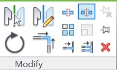
When you select an element in Revit, the ribbon displays a 'Modify' panel with two icons for pinning/unpinning (top right of the panel):

These icons are used as command functions to operate on the selected element(s); they also indicate what command is possible on those elements - in effect, showing the current 'pin state' of the  element, but in a confusing way:  the greyed out icon indicates the current state.
  • The lower right 'Pin' icon will be available if the element is not pinned
  • If the element is already pinned, it will be greyed out
 
  • The upper right 'Unpin' icon will be available if the element is already pinned
 
  • If the element is not already pinned, it will be greyed out
  • If multiple elements are selected, and some are pinned, some not, then both pin and unpin icons become available, so you can no longer tell the state of any of them from the ribbon icons.
 

Element Selection Pin Icons

The icons that display on the selected element operate in the more logical (but reverse) fashion - as well as being command functions when clicked on, they do actually indicate the current 'pin state' of the  element(s).
  • Each element has its own icon, so you can tell the state of each one.
  • Pinned elements show a blue 3D pin icon
  • Elements that were once pinned but are now unpinned sometimes show a blue pin with red cross - but it depends on how it was unpinned.
This is where it starts getting tricky:
  • If you click on the blue pin icon on the element, Revit now will show a red line through the pin to indicate it is now unpinned but was previously pinned - this can be a good reminder that you should repin it after performing some edit operation on it.
  • Revit remembers this 'previous pin state' even when you close the session and open the model again later - when you select the element it still shows the blue unpinned icon - I like to refer to this as temporary unpinning.
  • However, if you use the ribbon command icon to unpin, then the blue element pin icon totally disappears - I like to refer to this as permanently unpinning.
The keyboard shortcut to permanently unpin elements is ‘UP’. Multiple elements can be unpinned at one time using the UP shortcut.  There is no keyboard shortcut for the temporary unpin command.

This difference between the two operations is almost like a partly implemented idea for a proper temporary unpin command - I wish that Autodesk would take it one step further and give us a proper temporary unpin (or persistent pin):  this would allow us to unpin an element, then edit it, after which it would automatically repin itself.  There is a precedent for this in Revit with the temporary 'Exclude Options' selection checkbox (which rechecks itself automatically).
Feel free to vote for my Revit wishlist idea for Persistent Pins


Selection Settings

In the bottom right corner of the Revit window are the orange selection pin icons, although these perform a totally different function:
  • They display the status of whether you will be able to select pinned objects or not - they also operate as switches between the two modes.
  • The red cross on the icon means that you cannot select any pinned elements.

Refer to Hidden Commands - Selection Locks

Pin Visibility

Element pin icons are not always visible:
  • In a workshared model, when you select an element, it displays the 'Workshare puzzle' icon - this will obscure any pin icons
  • To see the pin icons you have to take ownership of the element(s)
  • you can click directly on the icon to remove it (and take ownership of the element), or right-click ‘Make Element Editable’ to take ownership and remove the puzzle icon.


Pin icons may also be hidden by group add/remove icons if you select an element inside a group without editing the group.


The way around this is to edit the group

Chain-Pins


Chain-Pinned ‘hosted elements’ (eg. Curtain panels) behave completely differently to normal pinned elements.  However, the icon for this is very similar - it has a chain link next to the pin.
The same pin/unpin commands and ribbon icons are used but they operate in a quite different way

Refer to Chained / Pinned Hosted Elements