
It is common for architects to need to calculate, check and record escape paths or egress travel distances in a building design. Revit does not have an inbuilt method for doing this. I've seen many suggestions on how to do this in Revit, but they are all pretty clunky, mostly involving several components and tags and schedules.
In Revit 2012, there was a new way to do this using adaptive components. I did not publicise this before, because there was a bug in the software that prevented it from working 100% reliably - but in Revit 2013, that bug has been fixed, so here is how to do it:
This method will create a 2D travel path (calculating distances in plan only).
- Create a new adaptive component (use "Generic Model Adaptive" template)
- Place a point on the intersection of the two reference planes;
- Place another three points in a line along the X axis, and
- Make all the points adaptive

- In Object Styles, make a new subcategory called "Escape Path", with a suitable linestyle – say red, dashed, heavy lineweight. Ensure that you choose the right category to put it under (generic, if that is your family category) – as all categories are listed.
- Draw a line between points one and two, using 3D
snapping.

- Change the line to the Escape Path subcategory.
- Join points 2 & 3 with a similar line, then points 3 & 4.
- Place a dimension between points 1 and 2, using the Ref. level as your work plane – this will give you horizontal measurements in plan. NB. Be sure to attach the dimensions to the actual points (not line ends) otherwise the reporting parameters will not allow you to use them in formulas.
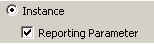
- Select the dimension, give it a parameter “Plan_Length_1”
- This must be set as an instance & reporting parameter
- Repeat
this process between points 2 & 3, then points 3 & 4.

- Flex the component by moving each point; NB. do not click and drag (it will move in z direction) - use the arrows
- Create a new Instance length parameter called “Total plan escape distance”
- Give it a formula: “Plan_length_1 + Plan_length_2 + Plan_length_3
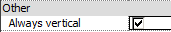
- Tick the “Always Vertical” family parameter – this will ensure that measurements
are always true in plan (they can be slightly out if you don’t tick this).
- Save and load the family into a project; and it should prompt for 4 points when placed.
- Once placed it should report back the total escape path length, in its instance properties.

- A counter (integer parameter) for the number of segments, using visibility to hide unwanted segments and calculations to remove them from the total; When placed in the project, it will still require all the adaptive points to be place, but it will just ignore anything after the required number in the counter.
- A user defined parameter for maximum allowable length;
- A calculation to see if the total length exceeds the maximum;
-
A
warning if the maximum is exceeded – this could either be a change of colour in
the lines, or else an element that is normally hidden, but has its visibility
turned on if the total length exceeds the maximum. NB. If
you want a text warning, it has to be done as model text nested in a generic
component loaded into the adaptive family.

- This example only has 4 segments, but you could add more - of course then you'd need more visibility and calculation parameters.
- You could also create a version that measures distances in 3 dimensions. To do that you need to host the reporting parameter lengths on reference lines drawn between each adaptive point - this would then measure the diagonal distance if any of the adaptive points are moved up in the Z direction.
- If you make the Total distance a shared parameter, then you should be able to schedule and tag it.

Please use this technique at your own risk - it is entirely up to you to check that it all works properly, and that it meets your local standards for egress travel distance / escape path measurement. Revitcat accepts no liability whatsoever for the creation and use of this technique. For this reason it is not possible to post a copy of this component here, so you need to create it yourself from scratch from a v2013 adaptive family template.

Youtube demo of escape path component in use
thanks for this post. what was the bug in 2012?
ReplyDeleteInteresting, but impractical. For any number of points different than 4, the user has to go to the family editor to fix the formulas, and fix the geometry. Imagine users at an architectural office calling the BIM manager every time the path is different. Until Autodesk includes a tool for this in Revit, I think that the old solution of a line based family does the job well and allows any number of clicks. For a reference, see this video:
ReplyDeletehttp://forums.augi.com/showthread.php?138757-Length-of-a-segmented-line&p=1169147#post1169147
Alfredo,
DeleteIf you look at the detail, you'll see that you can create a component with as many points/segments as you want (10 would probably suffice for most situations); the user then sets a counter for how many points they need; the component then ignores the points after that counter number (and hides the lines too). So, you really only need one component for most situations. Admitedly the user still needs to click to locate the redundant points, which might be a little confusing - a small price to pay for a component that gives instant gratification (no schedules or tags required).
I have not used this yet in anger, because of a bug in v2012 where the lines sometimes detached from the points. Fixed in v2013, but we are not using v2013.
Thank you, Tim, but I stand by my first opinion, that this is impractical. The operation is rather slow, and there are extra clicks to make. These tools have to be very practical in an office, where people are always in a hurry to produce and meet deadlines. And, the annotations are necessary on the plan view (the length and the arrow). So, it is not only impractical, but incomplete for the purpose. It is one of those cases in which adaptive components is simply interesting but not the most practical solution to a problem.
Deleteum. No. All they need to do is add the extra points once. Once its saved in the office library, its simple to deal with. I created one with 9 points to work exactly like the one shown here. If you know your way around family creation this is very practical. Its 2019, and this family works great!
DeleteIngenious but impractical as a work process. After all the methods I've seen, I've resorted to lines and simple totaling of the individual segments (I know, but gets the job done fast and doesn't over-complicate). I just wish the properties palette would give us the total length in a chain of selected elements, such as lines. Then we'll be much closer to a way to get this information fast(er).
ReplyDeleteHi Adriel,
ReplyDelete"SegNum" is just a check to make sure that a valid number is entered - if you put in any number less than 2 (1, 0, -1 etc) it resets it to 1; if you put in a value over 4, it keeps it at 4. Note that both parameters are integers.
I like to make families a bit foolproof if possible. I guess that you could have incorporated the check into "Total plan escape distance" but that is already long enough as a formula.
Adriel, I don't have time to answer properly just now, but you should be able to do it by using the "And" statement in the formula for its visibility - something like this:
ReplyDeleteVisible = and(SegNum=3, LengthExceeded)
It does start to get complicated when you have lots of combinations!
Adriel,
ReplyDeleteI'm glad it worked out. Sure, feel free to post a video of your work - just some credit for the concept would be appreciated.
I like your enthusiasm for it. Let me know how well it works on real projects as I am not using v2013 live yet.
Just did a demo of this at the Revit User Group Sydney meeting, and discovered that the current version of Revit now allows you to swap out families with different numbers of adaptive points. This means that you could have a suite of families each with an additional segment, and they could easily be swapped over if you need to add or remove a segment in the project.
ReplyDeleteHow about adding Groups to the type? Like if (GroupA, 250', 200') so that you could tell the line what occupancy group the area is and have the max travel distance calculated. Any ideas?
ReplyDeleteJust added a new post on this topic, with updated methodolgy using shape handle points.
ReplyDeleteBTW, sorry I didn't reply to your question 'Energy2Bless' about groups, but I didn't quite understand what you meant.
This is a simpler way to do it using detail/model lines even if it's not BIMish though :)
ReplyDeletehttp://puntorevit.blogspot.it/2013/12/chain-dimension.html
You can just use a spline can't you - it appears to give the correct overall length and can be bent around furniture etc
ReplyDeleteRevitCat, I love what you've done. It works great, however I'd love to be able to add a 2d plan view of a person at the start of the line segment and an arrow at the end. I have tried everything except the right thing to get this to work and align with the line segment path. Is it possible? If so, can you give me direction?
ReplyDeleteThat sounds tricky Charlie,
ReplyDeleteI don't believe it is possible to add any kind of 2D annotation to an adaptive component (have a look at my recent post on that subject - Reasons not to use Adaptive Components). So you would have to add another nested component or 3D element that you could turn on/off by visibility. To get the orientation working you could try nesting a line-based component between the last two adaptive points - but I had mixed success with that. You'd get better control over the orientation of the arrow by making it a two point adaptive component that is nested in and snapped to the last two adaptive points.
Alternatively, if you place a 3d element (arrow) into the main adaptive component, you'd have to host it to the reference line between the last two points, or onto the last adaptive point itself.
or you can just do them with a railing, configured as a very thin strip at floor level (or under it for not to show in all views. railings report total lenght.
ReplyDeleteI simply use a line based detail family and draw them on Egress plans. Then create a create a schedule and group by mark to sum all segments of each path. Add a formula in the schedule so that when a stair box is checked for a segment, the actual length is calculated using the sqrt(rise^2 + run^2).
ReplyDelete