This Revit feature really is obscure, and I can never remember how to do it without looking online for solutions. Plenty of people have posted on blogs and forums about this one, but I have my own slant on it. Most of the references to this are something like "How to create sectional perspectives in Revit" - and then describe how to apply a colour pattern to the cut surfaces of the section.

Applying Colour/Hatching to Cut Edges on a 3D View
1. 3D View.In fact this technique applies to any 3d view, perspective or otherwise - but only if a section box is applied as a view property:
2. Section Box
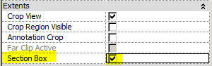
A section box will actually crop the 3d model (only in the view). This is not to be confused with Crop View and Scope Box which only crop the view, not the model.
Make sure that the extents of the section box are cutting the model where you want - drag the shape handles. In a perspective view it may not be so simple - other blogs describe this process well (Use View cube to temporarily make perspective orthogonal; adjust section box; rewind view back to perspective).
 |

There are several subtle settings that control how and when the coloured cut edges are applied:
4. Coarse Detail
- It only works when a view is set to Coarse Detail Level (not at medium or fine)

5. Coarse Poche Material
[Edit: This section added later]
Once the view is set to coarse, and has a section box activated, Revit will automatically apply the 'Coarse Poche Material' to any edges that are cut by the section box. This material is is controlled by a 3D view Type property - so it will affect all 3D views of that type.
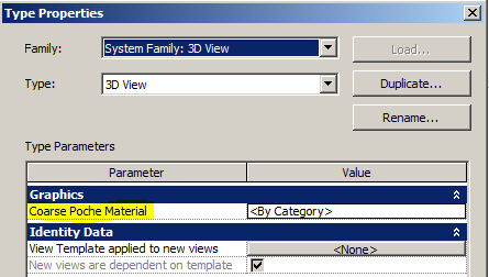
- In the standard Revit project template this property is set to "By Category", which means that nothing appears to change - it uses whatever the settings are for each category.
- In some project templates this value may already be set to a particular material, in which case that material will automatically be applied to cut edges. Typically that material would be a special material called "Poche"- this is a system material that is present in all templates (including families). [If you delete that material, it will pretty soon come back into your project or family!]
When you click on the value for the property, it will automatically default to the "Poche" material
Select the Poche material (or some other material)


6. Material Properties
- By default, the Poche material has a dark blue shading colour and NO cut hatching pattern - you can change this of course.
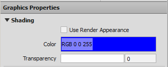
- This means that the colour will only appear if the view is set to Shaded, and not appear if the view is set to Hidden Line
 |
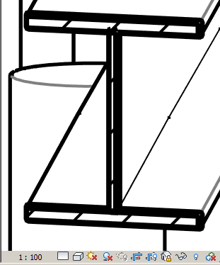
| Medium View, Hidden Line - No poche material is applied |
 |
| Coarse View, Hidden Line - No cut Shading visible |
- Once the view is set to Shaded, the shading colour appears - this is standard Revit behaviour, but in the context of the other variables it can be confusing
 |
| Coarse View, Shaded - Shading Colour is visible |
- You can also add a cut hatching pattern to the Poche material

 |
| Coarse View, Shaded - Shading & Cut Pattern visible |
- If you have a cut pattern defined for the material, you can revert to a Hidden Line view and it will display the hatching but not the shading colour (again, this is standard revit behaviour)
 |
| Coarse View, Hidden Line - Only Cut Pattern is visible |
- Alternatively you can use a solid fill colour for the cut pattern, and this will display on a hidden line view

 |
| Coarse View, Hidden Line - Cut Pattern (solid colour) is visible |
- If the shading is set to zero transarency, it will show neither the shading colour, nor the solid fill colour - ie. the clash makes Revit give up and show no poche.
- If you set the shading to semi trasparent, it shows the solid fill colour but at the shading transparency!!!

 |
| Coarse View, Shaded - solid fill pattern, 50% shading transparency |
No wonder I can never remember this setting - it is so obscure and has so many variables to juggle in order to get it working. If you forget just one variable, it may not work at all.
Checklist:
- Any 3D view (perspective, Isometric etc)
- Section box must be active (although it can be hidden in Visibility Graphics)
- Section box must cut through the model (Poche material only applied to cut surfaces)
- Coarse Detail Level view
- 3D View type properties - Coarse Poche Material property
- Poche material
- Shaded View shows poche Shading colour (and cut pattern if it has one)
- Hidden Line View shows poche cut pattern only (nothing displays if no pattern is set)
- Shaded View + Solid Fill cut pattern + Shading colour = ??