BILT Speaker

BILT Speaker
RevitCat - Revit Consultant
Showing posts with label colour. Show all posts

Sunday, 15 August 2021

Display Priorities of Solid Fill in Revit Materials

Back in Revit 2012 Autodesk changed the way materials work - so that they had separate graphics and appearance properties.  This was the start of much confusion for many users - and still to this day it catches people out.  You know the drill:  duplicate a material;  change its appearance properties and suddenly a hundred other materials change too . . . .

Well, I am not going to address that issue directly.  Instead I want to look at a more subtle confusion that some users encounter:  Exactly how do the different material properties display in each 'Visual Style' - it will not always be what you might expect or consider to be logical

Material Properties

In order to analyse this issue we start with two very simple material definition examples, applied to two elements in a Revit project:

Material 1 - Demo Generic

  • Light grey shading 
  • Light Blue appearance (different colour to shading)
  • no surface patterns


Material 2 - Demo Green

  • Light green shading and appearance;  
  • no surface patterns


Visual Styles

These materials display as expected in the various 'Visual Styles' in Revit - because we know that the graphic 'Shading' colour property matches the 'Appearance' colour property in material #2 but not in #1 

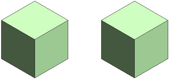
Material #1 on left,              Material #2 on right

Hidden Line Visual Style

Shaded Visual Style

Consistent Colours Visual Style

The colour displayed for material #1 (left) in Realistic and Ray Trace visual styles is different to shaded and consistent colours because the material properties do not match - this is to be expected.

Realistic Visual Style

Ray trace Visual Style

Material #1 on left,              Material #2 on right


Lighting

These views are lit with default sun and lighting settings (ie. light source over the right shoulder of the viewer)


Use Render Appearance

One thing that users often forget to address is consistency between the 'Graphics' and 'Appearance' colours.  If the colours are dramatically different, then materials look completely wrong, particularly in 'Shaded' views.

There is a quick and easy way to deal with this - it is the 'Use Render Appearance' checkbox to make sure the shaded colour matches the appearance colour.


This property can be used as a one-off operation - ie, tick the box to change the colour, then untick it.

Or you can just leave it ticked if you want the shading to update when the appearance property might change in the future.

  • NB.  Make sure that the appearance colour is correct first - as there is no 'Undo' so you might lose a shading colour definition.
  • Do not use this method if the shading colour is correct but appearance wrong


Surface Patterns in Materials

When you add surface patterns to materials is where things get more complicated . . .

We will make two more materials, based on the light green shaded material - these will use the same light green 'Appearance' (unchanged).

Material 3 - Demo Green Line Hatching

  • Light green shading 
  • Light green appearance;  
  • Line Cross-Hatching foreground surface pattern

Material 4 - Demo Green Solid Hatching

  • Light green shading 
  • Light green appearance;  
  • Line Solid Fill foreground surface pattern

Visual Styles

Hidden Line

  • Cross-hatch pattern is displayed as you might expect
  • Solid fill displays with solid colour - but without any lighting effects
Material #3 on left,              Material #4 on right

Hidden Line Visual Style

Shaded

  • Cross-hatch pattern is displayed on top of the shading colour
  • Solid fill displays replaces the shading colour - it is completely obscuredthis can be confusing if the user has not studied the material properties carefully
Shaded Visual Style

Consistent Colours Visual Style

Realistic (and Ray Trace)

  • Cross-hatch pattern are not displayed at all - unless a hatching pattern is defined within the material appearance (not a simple thing to achieve)
  • Appearance Colour replaces the Solid fill colour this is the reverse of what happens in a Shaded visual style - so it can be confusing
Realistic Visual Style


Background Hatching

Just for the record, here is what happens with background hatching - it follows the same rules as Foreground hatching.  [NB. This capability was added in Revit v2019]

Material 5 - Demo Green Line Background Hatching

  • Light green shading 
  • Light green appearance;  
  • No foreground hatching surface pattern
  • Line Cross-Hatching background surface pattern

Material 6 - Demo Green Line Foreground & Solid Background Hatching

  • Light green shading 
  • Light green appearance;  
  • Line Cross-Hatching foreground hatching surface pattern
  • Solid Fill background surface pattern

Visual Styles Materials 5 & 6

Material #5 on left,              Material #6 on right

Hidden Line

Shaded

Consistent Colours

Realistic


Conclusion

Solid Fill surface patterns are the one part of this Visual Style issue that cause display inconsistencies.

You may have good reasons for using Solid Fill surface patterns as part of a material definition - in which case go for it.  Otherwise, they are to be used with caution in normal Revit use.

Another approach to avoid the inconsistencies would be to make sure the appearance, shading and solid fill colours all match up.


Don't forget to check how many materials are sharing the Appearance asset before you change it - it is the number above the hand on the Appearance tab.


Friday, 16 December 2016

Applying colours and Materials in Rhino for Revit Import

Following on from my previous post about importing Rhino materials in Revit 2017.1   here is a brief description on how to set up the colours/materials in Rhino:

I am new to using Rhino, so my understanding of the UI and functions is pretty basic but I managed to figure out how to apply colours and materials to objects without reading any manuals.  I am happy to be corrected if there are better ways to do this.

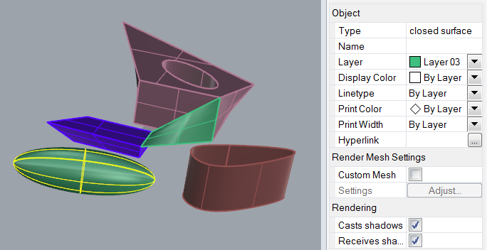
Once you have created an object (or multiple objects), you can select the object and view its properties.  Unless you tell it otherwise, it will be on the 'Default' layer, with Color, Linetype etc set to 'By Layer', which means that it will behave according to the layer settings.  During the new import process, Revit 2017.1 considers the default layer & colour not to be a material.
 

You can change the layer of the object from the Layer drop-down list, providing you have created new layers

By default, your file most likely will have no layers, so you need to create them, using the 'Edit Layer' function, available from the Edit menu.

Once the layers menu has been opened, it will be available under a Layers tab.  It has typical columns showing the name, show/hide, lock, display colour (just a box) and material properties for each layer.  New layers will have default settings (no colour or material defined), but these can be changed by clicking on the colour box or adjacent space under the material column.
If you are creating layers just to manage export to Revit, the names are irrelevant to Revit, but the colour and material are important - you don't need to get the colour/material right for its end use in Revit, as long as each object has a different colour, it will become a different material when imported to Revit.  The materials can then be edited in Revit.

If you expand the width of the menu it shows the material name (if defined), linetype and print width/colour - the print colour does not seem to be relevant for Revit imports.

Materials

You can define a material for use in Rhino, but the only thing that Revit takes note of is the material colour.
Rhino Material Properties

Object Properties

Normally, objects will display according the the 'By Layer' settings, which means that all objects on a given layer can have their properties changed together easily.
Object properties By Layer

You can override individual 'Display Color' for any selected object
Object properties By Object
If you choose a non-standard colour, it will show the colour name as 'Other'


SAT files

I tried exporting a coloured Rhino file to SAT format, then importing it to Revit, but sadly it did not bring the colours in as materials - so I am not sure what the trick is to assigning colours to objects in a SAT file.  I tested various ACIS versions of SAT format, to no avail.
Rhino Export SAT options
Does anyone know how to define colours for objects in a SAT file from Rhino?  Or from any other 3D modelling software?

Import Colours to Revit

For details on how these colours are imported to Revit, refer to importing Rhino materials in Revit 2017.1

  • It seems that Revit uses the display colours set in Rhino, not the print colours.
  • If you import two different Rhino files that have identical colour definitions, it treats them as different materials
  • If you import the same Rhino file twice, it seems that Revit assigns the same materials to objects in both instances
  • However, if you rename a material, or change its definition before importing the second instance, Revit will create new materials with a suffix of (2) added to the original name.  You could use this to your advantage if you want multiple instances of the same object but with different materials.

Sunday, 20 November 2016

Revit 2017.1 Import Rhino Materials

Following on from my post about the new Revit 2017.1 feature 'Import 3D Shapes', I have done some more testing on how to import Rhino files with materials (colours) into a Revit family.

If you import a Rhino file that has no colours or materials defined in it, you just get a dumb object in Revit that has no capability for controlling materials.


However, one of the subtleties of the new import shape feature is that it will recognise assigned colours in the Rhino file.  It will then create a new material in Revit for each colour.


To assign a material or colour in Rhino, you can either select an object and choose a colour/material;  or else you can create layers and assign a colour/material to the to the layer, then put the object on that layer and leave its object properties set to 'By Layer'.
Once you import the Rhino file to Revit, it will take just the RGB value of the defined colour or material and use that to create a new material in Revit - any other material properties will be ignored, so don't expect textures, reflectivity or anything else.
If you do not assign a colour/material to any object by either method, it will not be given a material in Revit (not even 'Default') - so you cannot subsequently change it.  Hopefully this will change in future versions of Revit.

The materials in Revit are given names such as 'Material 2' etc.  This is a big improvement over the confusing naming of imported Autocad materials (eg. Render Material 255-255-255).

The only property that the new materials have is a 'Graphics' colour definition.

It has default 'Appearance' settings (grey), meaning that realistic or rendered views will show grey objects.

You can of course change the material definition and give it 'Appearance' colours, tints, bump maps etc. 

This will only affect the part of the imported Rhino file that had that original colour (and now Revit material).
Realistic view with only one material Appearance edited

It would make sense to rename the materials so that they refer specifically to the individual objects within the imported file.  I like to set the 'Appearance' colour to match the Graphics colour, so that not only do the material previews show in colour but also any realistic views will display the colours rather than default grey.


I have not yet succeeded in testing this functionality with an imported SAT file (as I can't figure out how to apply colours in a SAT file), but hopefully it will work as a viable alternative workflow to the old method of importing/linking SAT files, as described in an earlier post.

For details on how to apply colours/materials to objects in Rhino, click here

Thursday, 29 September 2016

How to Find Linework Overrides in Revit

The Linework tool is much misused in Revit - it seems like a quick and easy way to make individual lines look the way you want.  In reality, it wastes much more time than it saves - this is because it is so hard to undo or change later on.  My advice to Reviteers is to use it as a last resort when every other method cannot or will not work - instead you should use sub-categories, filters, view visibility overrides or even object styles.

What does a BIM or Model Manager do to figure out when the Linework tool has been used?  Well, it is basically guesswork.  All you can do is set the linework linestyle to <By Category> and then hover the cursor over any lines that you suspect might have been tampered with using the Linework tool.

Why is this inconsistent with so many other Revit tools that have a 'None' option that sits at the top of the list?  Who knows - it is lost in development history, but it makes training harder.
And why is <By Category> not automatically at the top of the list?  I guess because it sorts alphabetically - but it is very irritating trying to find it in a list.

Once you have managed to select the linestyle of  <By Category> you then hover the mouse over the line and it will probably turn dark blue - which is not easy to spot on a large busy view.

Tip to speed up the search

I know of a quick tip that will help you in the search for overriden lines:
All you have to do is change the 'Pre-selection' colour to something brighter.
  • Go to Revit Options
  • Choose 'Graphics'
  • Spend 30 seconds wondering why 'Selection' and 'Pre-selection' colours are the same, and why dark blue, which is very hard to distinguish when most lines are black in Revit.
  • Spend another 30 seconds wondering which $#&*%$#* at Autodesk thought it was a good idea to make the default setting colours both dark blue.
  • If the colours are not both dark blue in your options, then you probably need to praise your BIM Manager for changing the Revit.ini file that is rolled out in your company.  Give them a gold star or buy them a drink
  • Change the 'Pre-selection' colour to something really bright like red (unless you are red/green colour-blind, in which case choose something else).
  • I like to change the selection colour too, although it is tricky to get a good selection that is not the same as sketch lines, and all the other special line types like Area boundaries.

Now when you hover the cursor over any line that has had a linework override applied, it shows up red (or whatever bright colour you chose) - don't forget that it only works when you have set the linestyle to <By Category>


I hope this saves someone, somewhere in the world a few minutes, and eliminates some anguish

Thursday, 14 April 2016

Weird stuff with Revit Line Weights

Following on from my previous post about line weights for material patterns, I have found some more weird things about Revit line weights that I never knew before:

1.  Pattern Line Weights

As Frank Giorlando rightly pointed out in a comment on the previous post:  Ceiling surface patterns use Line Weight 2.  So, if you want to control those independently, you should start your regular line weights from #3.
Thanks for that tip, Frank.

It would not surprise me if there are other categories that use different line weights again.

2.  Apply Button

The "Apply" button on the Line Weights dialog box does not appear to work - so if you start changing settings for different scales and want to check what happens (with hatching lines for example), you have to click OK to close the dialog box to see the effect.  I wasted a bit of time making changes that did not seem to be having any effect before I realised.  (as of Revit v2016 R2)

3.  Grid Line Weights

In testing the previous bug, I discovered some more weird settings:
Gridlines have all sorts of hidden away weight controls -
Unlike most elements, the actual grid line weight numbers are controlled from the grid Type properties (not from the Object Styles settings).  However, the Grid Heads have a master control in Object Styles where you might expect the gridlines to also be controlled

And something else I never knew:  The type properties for grid lines allow you to set different line weights, colours and styles for the centre and end segments - by choosing 'Custom' Center Segment..


Why would anyone want this?  I guess someone out there needs it and the programmers thought it would be useful.  Personally I would have been happy to see the weight set in Object Styles, with Visibility Graphics overrides if you need them - like most other categories.  This just seems like an unnecessary complication and inconsistency.

[Edit: Steve Stafford has previously blogged about how and when to use the Center Segment setting in this link.  I can see that you might well want to have a gap in the grid, but I still can't imagine why anyone would want a different line weight - just to make their drawings look ugly?  This also highlights the radically different way to control breaks in the middle of gridlines vs breaks in the middle of section lines - oh, I wish we had more consistency in UI and methodology in Revit]

4.  Dimension Tick Line Weights


Another category where the line weights are controlled in the Type Properties is Dimension lines.  The line itself and the dimension 'Tick Mark' have independent weight settings (at least both appear to be in the same place, unlike grids and grid heads).

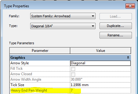
But when you go to the arrowheads dialog box and check the settings for the Tick Mark, there is another weight control called "Heavy End Pen Weight".  Now someone is showing their age by using the term "Pen" in there!  Most of the time it is greyed out and has no effect, but if you cycle between the different Arrowhead Types, each one has a different value.  Why?

Well, if you change the Arrow Style to 'Heavy End Tick Mark' it enables that setting and you can change the number.  If you change the Arrow Style back to Diagonal or Arrow, it greys out the number but remembers it - I guess it does nothing.  I decided that I do not want to know what a Heavy End Tick Mark is nor why it needs its own special setting that causes confusion to the other arrow styles - it is a 'rabbit-hole' I don't want to go down any further!

Note the mix and match of imperial and metric units that came straight out of the v2016 metric sample file.  Sloppy work by someone there!

[Edit: Steve Stafford has blogged previously about when you might use Heavy End Tick Marks in this link]

Really Weird:  Line weights in Perspective Views