BILT Speaker

BILT Speaker
RevitCat - Revit Consultant

Tuesday 16 December 2014

Revit's Most Hidden Commands (part 2) - Tag Units

Changing the number of decimal places on a dimension is relatively straight-forward in Revit once you know how to do it:

Method 1 (Project Units):
  • Click on the Project Units icon on the manage menu
  •  Click on the desired units (eg. length)
 
  • Change the number of decimal places as desired
  • And don't forget that handy "Suppress trailing zeros" setting to keep your drawings less cluttered (although I'd prefer it didn't have that redundant apostrophe on the dialog box!)
  • This will affect all linear dimensions in the project , except where this setting has been over-ridden - in which case go to method 2.
 Method 2 (Type Properties):
  • Select a dimension 
  • Click on Edit Type
  • Click on the parameter called Units format 
  • Click on the "Use Project Settings" checkbox; 
  • Alternatively,  change the number of decimal places and it will over-ride the project settings just for this dimension type.

That is a sensible Revit-like workflow once you know the process.
But, have you ever wanted to change the unit properties on a tag?  That is a whole different story . . . .
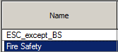

Tag Units

Each time I need to change tag units, it usually takes about half an hour to either remember or figure it out.  Here is the process I usually go through:
  • Select a tag

  • Edit type to see if it has unit over-ride properties like a dimension
  • Er no, nothing useful there
  • Hmm, what next?  
  • Try changing the project units
  • No, that doesn't work either
  • Oh, maybe its set in the family?
  • Try editing the family
  • Changing the project units in the family make no difference back in the project
  • Try selecting the label that has the value in it
  • Check its type properties
  • No, nothing there
  • Hmm, running out of options here
  • Ah, try Edit Label
  • Can't see anything that lets me change the units here
  • Click on the label parameter itself (on the right hand side)
  • Oh, what is that tiny, tiny 'hand' icon that has come to life down the bottom of the dialog box?
  • Click on it anyway, just to see
  • Oh, finally we get to a units format dialog box

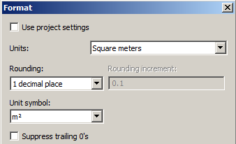
  • Change the number of decimal places,
  • or better still, click on the Use Project Settings checkbox so that it can be controlled back in the project (unless you need individual control just for this tag family
If you follow the logic of why it is done this way, you can see that you may need to have the flexibility to have different units for each parameter in each label in a tag - but wow, is it an obscure process.  99% of the time most people would be quite happy with type parameters in the family in the project (like dimensions).

Since it only needs to be changed about once a year I always forget, and have to figure it all out again.

Label unit format icon - is it a hand or a subtle method of torture?

Thursday 11 December 2014

Revit Stair Treads - Minimum Widths

When editing Revit component stairs, have you ever encountered an error message where it tells you that the actual tread width is less than the minimum allowed tread width, when in fact the two values are identical?

Usually it allows you to set tread widths the same as the minimum allowed value, but occasionally not.  I suspect this occurs when you mess with the minimum allowed value (a Type property of the whole stair) - perhaps when you increase the minimum to match an actual value that is already modelled.

My solution is to change the actual width value to be say 1mm more than the minimum, then change it back again so they are the same - error message gone.

Tuesday 9 December 2014

View Filter Sort Order in Revit

In Revit, View Filters are not automatically sorted in the 'Visibility Graphics' dialog box - meaning that you often get a jumbled list that is really hard to read. [Edit: There is good reason for this - the order of the list is the order that filters are applied, from the top (as pointed out by Steve Stafford);  but sometimes you just want all similar filters listed together so it is readable]

Recently there has been a subtle change to how filters are added to the list (in v2015 of Revit):

In Revit 2013, when you add view filters, the most recent one will always be added to the end of the list.

In Revit 2015, when you add view filters, they appear to go in just below the selected filter in the list.  Once you add a new one, it does not become selected.  That means that if you add several in succession, they won't go in the order you add them - they will be added in reverse order just below whatever you happened to have selected.

To correct the Sort Order:

Initially I thought that you either have to live with the mess, or remove the filters and add them back in again.  Of course, if you do this, you lose all the filter override settings.

We actually have the ability to move filters up and down the list (Edit. Thanks to various comments - this paragraph has been corrected).

Revit 2015 - Adding new filters
  • Click on the filter in the list that you want new ones to follow
 
  • Add the first filter
  • Then click on the one you just added
  • Add the next one
  • Click on that one
  • Add again
  • etc - until you have the list as desired.

If at any point you forget to select the last one before adding the next one, all is not lost.  All you need to do is to move it up or down the list

This method does give you much more flexibility than how it worked in v2013.  However, it is confusing as hell until you see what it is doing.

I noticed that you can also add several filters at once, but it does not necessarily add them in the order that they are shown in the 'Add Filters' list.

There is also the curious question of why the list of filters in the Filter dialog box is not alphabetical.  Only Autodesk can solve that for us . . . . .

Monday 1 December 2014

Best Tall Building in the World Documented on Revit

One Central Park in Sydney recently won the "Best Tall Building Worldwide (2014)", awarded by the Council on Tall Buildings and Urban Habitat (Chicago).

Designed by Ateliers Jean Nouvel, in association with PTW Architects in Sydney.  All the architectural documentation was done by PTW using Revit in Sydney.  This was an extremely complicated Revit model to work on, partly because no two floor plans were identical.  The building consists of a six storey mixed-use podium with a partially underground retail level and several levels of basement parking; and two towers of different heights.  The lower tower has an array of heliostat mirrors mounted on top - these track the sun and bounce its rays up to the underside of a massive cantilevered roof garden;  the cantilever supports another series of mirrors, which reflect the sun back down into the public garden behind the building, and also into the shopping atrium in the podium.

Array of mirrors cantilevered from the upper tower
Cantilevered mirrors viewed from inside the podium atrium
A series of fixed green walls are located in varied positions and heights around the building;  the residential zones also have planter boxes which are arranged in a pattern that repeats every three floors.  The combination of the repeating pattern and the varied height green walls gives an overall irregular look to the building;  it also means that no two floors are exactly the same - an unusal feat on a building of this size.
Green planters on the balconies
The cantilever structure not only supports the mirrors but also a roof garden for the penthouse apartments.  From this roof garden is visible another building successfully documented on Revit by PTW Architects:  the Channel 7 studios and offices at the Australian Technology Park - visible through the glazed railing.

View of Channel 7 headquarters from the cantilevered roof garden
The roof garden is linked to the penthouse floors by a red-glazed bridge, which is not for the faint-hearted to walk through.

Link bridge to cantilevered roof garden - with red glazing
The documentation was started in Revit v2009 and completed in version 2011, on computers that only had about 8 to 12Gb RAM, so they really struggled with the large file sizes.  The size of the project and the differing floor heights of the towers meant that it was modelled in a series of linked Revit files - with all its attendant problems of linked views and tagging elements in linked files.  Worksets were an invaluable tool for handling all the different links on computers with limited RAM.

We also used RTV Tools "Drawing Manager" to handle Revision control and the complex sheet numbering system required by the building contractors.  It was invaluable for handling revisions across sheets on multiple linked files; and for batch generating PDFs and DWGs with the appropriate file names for uploading to Aconex.

Although this project was basically done as "Lonely BIM", there was some collaboration - particularly with the steel fabricators.  This project was a successful testing ground for how to handle such a large and complex project in Revit.  Many people worked on the project over the years, and are now applying that gained knowledge in different locations and on varied projects in Sydney and around the world.