BILT Speaker

BILT Speaker
RevitCat - Revit Consultant

Wednesday 30 April 2014

Reasons to be Cheerful - about Revit Adaptive Components

Why did I publish a list of Reasons not to use adaptive components in Revit when I have previously published so much good stuff about them?  Well, it is because they have so much potential to allow us to do wonderful things in Revit - but it is largely unrealised potential for the average Revit user.  We need Autodesk to remove those "reasons" so that we can start to use adaptive components in everyday life, instead of just for specialist situations.

However, Adaptive Components can be used to do amazing work, so I need to redress the balance of the previous negative post with this list of positive reasons for their use.

Adaptive components started out life as a special tool for filling in edge pieces on mass surface patterns.  From there they have developed into a totally different beast.

  • Multiple placement points can be used to control orientation in 3 dimensions (unlike line-based families that can only rotate in 2 dimensions).
3 point adaptive tubes
  • Multiple placement points can be used to control the scale of many and varied parts of the family - just by the spacing of the adaptive placement points
3 point adaptive tube placed at varied angles and lengths
  • Adaptive points can snap to elements in 3d space, and remain linked to the vertices of those elements - which become hosts - perfect for tensile structures (just remember never to delete the hosts):

4 point adaptive component tensile canopy

  • Points!  These are wonderfully powerful elements in the mass/adaptive family environment - I miss them back in the traditional family editor.  They can be used to host and control other elements, once you understand them.
  • In v2014, three points can host an arc by start, end,radius - this cuts out lots of trigonometry and formulas

  • Points can also be hosted on lines, arcs, etc - they then take on different, very useful properties 
Points hosted on lines and intersections
  • Points can be used to control rotation within families.  Wow, no more reference lines and dodgy angle parameters!  thanks to Alfredo Medina
 
  • Divide Line & Surface commands are available in the mass/adaptive family environment - they cut out a lot of the work we previously had to do with formulas.
 
  • Repeaters - the adaptive version of the Array command, but oh so much more powerful than traditional arrays.
Calatrava - Station roof support using nested repeaters, hosted on divided paths on geometry hosted on points!

Now, if only we could use all this stuff in the traditional Revit family editor . . . . . or else have all the traditional functionality in adaptive components . . . .  then Revit would really rock!

Friday 18 April 2014

A Dozen Reasons Not to Use Adaptive Components in Revit

I love the idea of Adaptive Components in Revit - they have so much potential to allow us to break free of some of the traditional constraints of Revit.  But it is early days in their development - they have many of their own limitations.

However wonderful adaptive components are in Revit, they do have some downsides.  I have heard suggestions that we should all use adaptive components all the time instead of traditional Revit families.  Here are some reasons why you might not want to do that - and perhaps Autodesk can treat this as a checklist of things to address so that we can use them in more situations:

  1. Adaptive components do not have any 2D or 2½D capability - there is no Annotation tab in the adaptive family editor.
    - No text within Adaptive Components
    - No symbols
    - No symbolic lines
    - No detail components
    - No filled or masking regions within Adaptive Components
  2. You cannot add model text within Adaptive Components (except by nesting a traditional family with model text in it).
  3. Adaptive family file sizes can get extremely large, especially when you start nesting them or use repeaters. They don't seem to have the same capabilities of minimising file sizes that traditional families have when multiple instances of nesting occur.
  4. Visibility Settings are not obviously available in the UI within Adaptive Components (for controlling display levels and 2d view visibility) - [Edit. need to select an object and right-click to get to visibility]
  5. Controls are not available within Adaptive Components (for controlling flipping component orientation) - this is somewhat understandable as it could get complicated with multi-point adaptives;  nevertheless it is a limitation.
  6. If any one adaptive point is snapped to (hosted onto) an element that is subsequently deleted, the entire adaptive component also gets deleted, no questions asked.  Scary huh?  [Edit. I even found one situation where just duplicating the type of the host sent the adaptive component off into oblivion ! ]  This means that adaptive components behave more like true hosted families (doors, windows) that are completely dependant on hosts;  it would be much better if they behaved like face-based families that exist quite happily after their host face is deleted (refer to Chris Price's blog on Face Based Families).
  7. Placement of adaptive component points in the project do not lock to orthogonal - they do not use the Revit smart snapping capability, except for snapping to vertices and edges.
  8. Placement of "Site" category adaptive component points in the project do not snap/lock onto toposurfaces, unlike traditional site families.
  9. You can copy levels in adaptive families but they do not behave like two-level families (columns, generic) that have the levels baked into their templates, which then automatically lock to assigned levels in the project.
  10. Adaptive components cannot have a host element baked into the template – so it is not possible to include a void element in the adaptive component that will automatically cut the host face it is placed onto.  “Cut with voids when loaded” capability is very limited in categories it can be applied to – it cannot cut curtain panels, curtain systems, mass categories etc.
  11. As adaptive family templates do not contain any host elements, it limits the possibilities for using reporting parameters within formulas to adaptive points only - no wall thickness dependant frames etc.
  12. If you tag an adaptive component that has more than one adaptive point, the tag moves if any of the adaptive points move in the project - meaning that annotation on drawings will become even more unstable. 
  13. [Edit. Make this a "Baker's Dozen" as I forgot a really important one:  The list of categories available in adaptive components is seriously limited.  Most structural categories are missing!]
Adaptive Categories

This is not a list of reasons to never use adaptive components.  It is more a checklist to warn you of some limitations , so that you can plan when best to use them.  The list is not comprehensive - for example, it does not address issues of hosting, and analysis that might be vital for MEP or structural families. This list does not address the operational differences or difficulties within the adaptive family environment - for more detail on this, refer to Rival Revit Environments.

Don't plan to replace your traditional Revit library with an adaptive version just yet.
But there are Reasons to be cheerful about adaptive components.

Friday 11 April 2014

New in Revit 2015 - Schedules & Parameters

We still don't have a definitive list of what is new in Revit 2015, but here are a few more details about some of the new features - with the proviso that I don't have my hands on the final release version so I can't be a 100% sure I have the details right.  But you will be able to test the software as soon as you have it, and you'll know what to look for.
[Edit:  Autodesk have now published their v2015 help online, including the Whats New in 2015 section;  be sure to check out the Upgrade Information section]

Parameters

Parameter Reorder

Up until Revit 2015, the sort order of Revit parameters in the family editor and in the project was a mystery to most people.  It starts off adding parameters in reverse alphabetic order;  but as you start changing parameter names it soon goes haywire and the order becomes unpredictable.  Various people have come up with ingenious workarounds to reorder parameters but those methods are painful to say the least.  A fix for this problem has been on wishlists for Revit from the early days.  In Revit 2015 a partial solution has been applied to a very tricky problem to solve.

This new feature has several parts to it:
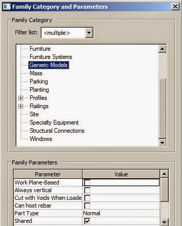
1.  You can change the order that new parameters will be added in the family editor
  • It can be set to ascending or descending alphabetic order.

  • You might think that it will be a simple decision to make it "Descending" as this is how almost every (latin) alphabetic list is sorted.  The one exception to this in Revit is how the family editor used to work - reverse alphabetic (to start with).  So if you want semi-consistency with all your old Revit families you might go with the old method of "Ascending".
  • Personally I will set it to the normal alphabetic order "Descending" as soon as I get my hands on it - so that we can start getting some logic to new families (the old ones are all mixed up anyway).
  • If you change a parameter to a different group heading, it will honour the sorting order within that group - this may be a kind of workaround for reordering, rather than using the Move Up/Down tools described below.
  • This sorting order setting will not affect parameter order in existing families.
  • Will not control system parameter order (not visible in family editor)
  • Will reorder by standard unicode ascii character order - this means all special characters (accented letters) may go after the 26 characters used in English.  This sort order may not work so well for other languages (I am not 100% sure about this one).
2.  You can move individual parameters up and down in the list
  • If a particular parameter is not inserted in the order that you want, you can use the "Move Up" and "Move Down" buttons to get it in the right place
  • I believe that it only allows you to select one parameter at a time to move up or down.
  • You could obviously use this feature to reorganise all your old families - but I can't see myself laboriously going through thousands of familes, moving parameters one by one to fix them up!
What we really need is a batch method to reorder parameters in existing families in a library.  I believe that Revit 2015 may have some sample API code that could be used to do this - but you would need to compile that yourself.  If you haven't learned how to do that yet, it will be another skill you need for rolling out 2015 to get the most out of this new feature.
No doubt someone will write/compile the API fairly quickly, and hopefully post it on the web for us to use.  [Edit:  refer to the Upgrade Information section of Autodesk Whats New help online - it refers to the Software Developers Kit (SDK), but it does not say where to find the necessary code sample]

I would prefer to have it built in to the batch family upgrader that is supplied by Autodesk;  I believe that Aaron Maller may have devised a clever way to use journals to get this happening? 
I understand why an "automatic re-order on upgrade" is not built in to the software as it would not suit everyone.

Tooltips for parameters 

In the family editor, you will be able to add tooltips to each parameter that you create (or have created in the past).  This is accessible from the Parameter Properties dialog box.
This is a really cool little new feature, which works well.  It will enable you to give instructions to users about what the parameters might do and how to use them -
  • It has a character limit, which I think is about the same as a tweet, so most people should be able to cope with that.
  • The tooltips will show up in the project environment when the user hovers the mouse over the parameter.
  • Obviously this won't apply to system parameters as you cannot access them in the family editor.
  • You probably won't go back over old families adding tooltips to all parameters, but certainly it will be worth doing so for the cryptically named ones.  
  • Hopefully it will be possible to access this capability in the API in which case someone will probably write a tool to speed up the addition of tooltips to old families
[Edit:  NB. You cannot add tooltips to existing Shared Parameters - refer to Shared Parameter Tooltips]

Shared Parameters for View Titles

You will be able to add shared parameters to view title families - this will be done by editing labels in the family editor.  I see this as useful for things like bilingual drawings where you want two (or more) languages on each view title.

Schedules

Images in Schedules

Revit 2014 introduced the ability to insert images to schedule headers.  In v2015, images will now be able to be put into the body of schedules, linked to instance or type parameters. The purpose of this is for such things as room data sheets - which is something that many people want to be able to do. 
I find that prospect really scary for a number of reasons:
  • Images cannot be linked into Revit - only imported (Aaargh!);
  • There is no method of controlling file sizes during the import process (unlike many email image attachment programs that let you reduce file sizes);
  • Project pressures and human nature is such that very few people take care to check image file sizes before they are imported;
  • We do not have proper image management tools in Revit - we need to be able to locate all instances of any image regardless of whether it is placed or not. [Edit:  The Autodesk online help tells us that the "Manage Image" dialog now has listings for Count and Path - this will help with tracking down some of those images, but it really needs to report the image Size too]
This means that our Revit project file sizes could be blown out of the water very rapidly unless great discipline is used to manage this process.

There are a number of other limitations to this new feature:
  • You must create the images - Revit cannot use the automatically created family previews in schedules.  It would be good if it could because they are already small file sizes
  • Schedules cannot be placed to automatically flow onto multiple sheets when they get too long to fit on one page, so this is only going to work if you place the schedules on large drawing sheets.  This kind of schedule is typically done on small sheet sizes (A4 or Letter)

Schedule More Parameters

More Wall parameters can now be scheduled:
  • Base Constraint
  • Base Offset
  • Top Constraint
  • Top Offset
  • Unconnected Height
What is not included in this list is "Top is Attached" or "Base is Attached".  I find this really worrying because it means that when a wall is attached at top or bottom, the "Unconnected Height" is almost certainly going to be displaying a false value in the schedule.  At least in the properties dialog you can see those "Attached" checkboxes so it might alert you to the issue.
If we could also schedule the "Attached" properties then we could use the schedule to identify attached walls, and perhaps use conditional formatting to highlight possible false height values.  Lets hope it makes it into v2016 . . . .

The same problem could also happen if a wall has had its profile edited - again the wall heights could be scheduling false values.  This is not so simple to solve as there is no property for "Profile is edited" - however, Revit knows if it has been edited or not because it displays a "Reset Profile" icon in the ribbon if a selected wall has had its profile edited
More detail on this issue in this blog post

Custom Total Titles

You will be able to specify custom text to display for the Grand Totals title on the Sorting/Grouping tab of the Schedule Properties dialog.  This is one more small but welcome step in the process of improving schedules in Revit.

For info on other new features in Revit 2015, refer to Sketchy Lines

Sunday 6 April 2014

Adaptive Component Origins in Revit

Have you ever wondered how Revit manages the "Origin" (X,Y,Z = 0,0,0) of an adaptive component?
It is somewhat different from the way it handles origins and insertion points of traditional Revit families.  So here is an analysis of the differences between the two.

Traditional Family Insertion Points

A traditional Revit family typically has three reference planes that intersect at the origin point - representing the X, Y and Z axes.  To start with, the origin is the same as the insertion point when the component is placed in a model.  For this discussion we will only think about the X and Y axes in plan because the vertical insertion point (in Z axis) is locked to the level (in the family) and does not change (unless you use the Offset property - see below).
At some point those X and Y reference planes might be moved within the family.  This may or may not affect the insertion point, depending on the reference plane properties:
  • If the reference planes are moved, and they are set to "Defines Origin" then the insertion point will move to the intersection of the two reference planes
  • Alternatively, one or two other reference planes might be set to "Defines Origin" - if they are in the X or Y axis, they will take over the origin property from the Centre reference planes (and the centre reference planes will have that property unchecked);  if the other reference plans are not orthogonal then Revit will ignore that setting, and use the centre reference planes or the original origin point.
  • If no reference planes in the family are set to "Defines Origin" then the insertion point will remain at the original X=0, Y=0 origin
  • If only one of the reference planes is set to "Defines Origin" then the insertion point will be at the intersection of the "Defines Origin" reference plane and the original perpendicular axis.
  • If the insertion point of a family is changed and then reloaded into a project  where some have previously been placed, it will overwrite the family definition in the project and will move the geometry in any placed components of that family (by the same amount that the insertion point moved).
For this reason it is good practise to make sure the two reference planes that define the insertion point are not moved from the origin once you have decided where it needs to be (keep them pinned).  Geometry should be moved relative to the origin if need be.

Hot Tip:  If you lose track of the true origin, just create an Autocad file with a cross intersecting at X=0, Y=0.  Save the dwg and import it in to your family at "Origin to Origin"; trace over the cross with reference planes or lines; delete the dwg; purge the dwg (since you can't link dwgs into a family, you need to import, then purge).

Offset.
Most traditional unhosted Revit families have an "Offset" system parameter that is automatically created when you load the family into a project (this contols the Z offset from the placement level or workplane).  Recently we found some old plumbing families (baths) that did not have the Offset parameter - we believe that this is because they were created from very old family templates that pre-date the addition of this offset capability, from the dim distant Revit past.  Hosted and face-based families usually have an "Elevation" system parameter (rather than Offset), which works like Offset but only in the project vertical axis, whereas the Offset parameter works in the local z axis of the family, which may not be vertical in the project.

Adaptive Family Insertion Points

Adaptive components behave in a different way.:
  • Although they have a true origin with two reference planes intersecting there, the insertion point can be overridden by adaptive points.
  • If there is no adaptive point in the family then it behaves almost like a traditional family, except that the "Defines Origin" parameters appear to make no difference - the origin and insertion point remains at 0,0 regardless of whether any reference planes have that property checked
  • If there is an adaptive Placement Point in the family, then Revit uses that as the insertion point of the family;  however it still remembers the true origin
 
  • If the only adaptive points in the family are Shape Handle points, then Revit uses the traditional origin as the insertion point (not the adaptive point)
  • If a placement adaptive point is deleted (in the family) or changed to a shape handle point, Revit does not move the geometry when the family is reloaded into a project.  This is because Revit knows and remembers where the origin is even though it uses adaptive placement points for insertion - this is logical but can get confusing.
If a placement adaptive point is moved (in the family) then reloaded into a project it might move geometry of previously placed components - it depends if the geometry is hosted on the adaptive point or not.   In this example the hexagon is hosted on the adaptive point;  the circles are just placed on the level workplane, close to the origin point.
Geometry in the family
Geometry in the model
  • Any geometry hosted on the adaptive point remains where it was in the model when the family is reloaded; 
  • Any geometry placed in the  family but not hosted on an adaptive point will move relative to the 0,0 origin point - so if the adaptive point is moved/flexed in the family it will end up a different distance from the point in the family;  when reloaded, the unhosted geometry will move in the project so that it retains that distance, while the hosted geometry remains put at the insertion point
 
  • Once you are in the project environment, and you move the adaptive point, something different again happens:  all the geometry in the family moves together! (this can be hellishly confusing).
Offset
Adaptive components do not have an Offset system parameter.  Instead they have an "Elevation" parameter, which does not appear to do anything - neither unhosted elements nor elements hosted on adaptive points will move when this Elevation value is altered.

Adaptive Component Reference Planes

Most adaptive component demos that I have seen show the placement of adaptive points in random locations in the family.  Why?  Probably just because you can.
I am more careful - I always put adaptive point #1 at the origin (intersection of the two reference planes that exist in the family template).  I do it for a reason, even though it takes a few extra steps - I have to go to a plan view because points won't snap to ref plane intersections in 3D.  If there is a second adaptive point I will snap it to the X axis for the same reason:  . . . .
  • Let us assume that you place an adaptive point in a random location;
  • Make it adaptive
  • Then place some geometry associated with the point (set the work plane to its horizontal plane first)
  •  You could place a dimension just to check how far it is from the origin
  • Load the adaptive family into a project and place one (it uses the adaptive point for insertion)
  • Try placing a dimension to roughly the same distance from the adaptive point as it was in the family - the hidden reference plane in the family will highlight and allow you to snap to it
  •  Once you place the dimension, the highlighted reference plane disappears
  • You could do the same with the other axis reference plane
  • Revit will attempt to snap to those reference planes and their intersections during many other commands that involve snapping - even to remote objects.
Its not very helpful is it?  In fact it is downright annoying when you have lots of adaptive components placed.
  • Imagine what happens when you have two adaptive points placed in the family at random, with some geometry between them?  

  • The hidden reference planes are now at crazy angles in the project and cause all kinds of random snapping locations

Hot Tip:  In v2013 the developers gave us a solution to this issue by enabling the  properties of those reference planes to be set to "Not a Reference" [that did not work in v2012, I think]
Good Practise: 
  1. Chances are that you will forget to change this setting some time, so it is a good idea to get into the habit of putting adaptive point #1 at the true origin, and point #2 on the X axis so that these reference planes will be orthogonal to the geometry.
  2. Whenever you flex the family by moving the adaptive points, remember to put them back to where they were, so that you don't get strange behaviour where unhosted elements in the family might move in the model when you reload the family into the project.

For more differences between traditional and adaptive families refer to Rival Revit Environments

Tuesday 1 April 2014

New Sketchy Lines in Revit 2015

The big new feature for architects in Revit 2015 is the Sketchy Lines setting for views.  I have found some interesting subtleties in the way that it works.

In the Graphics Display Options dialog box there is a new section for "Sketchy Lines"
  • Firstly there is an "Enable" checkbox to turn the effect on or off - initially it seems to do nothing because the default slider settings are zero.
  • Jitter does two things:  as the slider increases, all the straight lines in the view become more wavy;  at a certain point the lines start doubling up, and then becoming multiple lines - so you get a combination of the two effects somewhat like running a pencil back and forth to emphasise a line.
  • Extension does what you expect from the name - it "virtually" extends the lines past their real end points or intersections.  The extension obviously increases with the slider value, but it is not an equal extension on each line - it is proportional to the length of the line

It seems like the line extensions and jitter are applied to the model before any hidden line removal is done - this means that all lines are jittered/extended even if they would ultimately not be visible in a normal hidden line view.  This has some unexpected side effects that you need to be aware of:

Jitter

  • Jittery lines seem to be actually waving in 3D, which explains why you will see sections of jittered lines disappear as they duck into or behind an adjacent surface.  On the roof in the Revit sample file that looks quite good because you don't want to emphasise the roof stripes.  Once you bump up the level of jitter past the halfway mark it starts to create multiple lines so that in most instances where a line partially disappears another one will be waving the other way so it remains visible.
  • On an outside edge the effect is less obvious - in fact it tends to emphasise horizon lines as the lines are less likely to be hidden by adjacent surfaces.
  • On an inside edge the effect is the opposite - the lines are even more likely to disappear as they have much more chance of being hidden by a surface - have a look at the coving on this image
  • Jitter is applied equally to all lines, categories, element types, internal and external edges, silhouettes, depth of view, scale etc.  What this means is that some elements get much darker as soon as you enable jitter - such as railings and window frames.  This is partly due to previously close parallel lines now overlapping, but also due to the multiple line effect on higher levels of jitter.  It is currently not possible to be specific about which elements become more jittery than others.  It may become necessary to start applying overrides like halftone to certain categories, so that they do not dominate.

Extensions

  • Line extensions can have unexpected results if you bump the slider up too high - lines from elements that should be totally hidden can start showing through surfaces.  On the Revit sample house there are some internal walls (?) that start to project through the roof;  balcony lines project right through the side wall.  
  • This effect is also dependant on the overall line lengths, as shorter lines generally extend less at their ends.  The overall effect is more sketchy but the random lines might confuse people - so you need to balance the extension settings to match your desired effect.
 
  • If you have a few persistent line extensions you can always use the Linework Tool to make them invisible.  Likewise where jitter makes too many lines on a particular element - the Linework Tool will be your friend (or enemy if there are too many lines and not enough time!).

Settings

In order to get the effects that you are happy with you'll need to experiment, but it is probably a good idea to set both sliders at 3 and start from there.  The sketchy line effects are going to look better if you use them in combination with other view-based settings such as Smooth Lines, Ambient Shadows and Gradient Backgrounds.  It would be nice to be able to create standard combination settings of all these effects, to apply at one click.