BILT Speaker

BILT Speaker
RevitCat - Revit Consultant
Showing posts with label height. Show all posts

Tuesday, 8 February 2022

Stepped Handrail on Stepped Stairs in Revit

A couple of years back I posted on how to create a stair with stepped sides


I always intended to follow it up with what happens to the handrail, and how to solve it?  Well, it is never too late.


Just in case you are wondering how to create the stepped side to the stair run in sketch mode - here is a trick for creating a DIY array in Revit.


When you create a stepped boundary for a stair run, the handrail also becomes stepped, but it is pretty clunky.


Baluster Placement

The first thing to notice is the hideous baluster placement - it is placing one at each change of direction, and one (or more) in the middle of each segment.

To tidy it up:

  • we will probably have to create a new railing type (to avoid messing up the straight railing on the other side of the stair
  • then edit the railing type properties; and the baluster placement
  • Untick the checkbox for 'Use baluster per tread on stairs'


  •  Balusters will only be placed at ends of each segment

Alternatively you could try the opposite: keep the Baluster per tread, but remove the start and end balusters - but then you lose control of the baluster locations in the segments running parallel to treads (not centred).


Top Rail Properties

You may not like the clunky Art Deco look of the vertical "Gooseneck" handrail segments, so the first step is to tab-select just the top rail (not the whole handrail) - then look at its Type properties

  • Change the Transitions from 'Gooseneck' to 'Simple' (or None)
  • Revit will give a not very helpful "not continuous rail" warning:
  • Whichever you choose (Simple or None), you get 'None', as Revit has a headache and thinks it is all too difficult, so it simply can't be bothered to join the segments

Edit Railing Segments

The next thing to try is editing the whole railing path:

  • Select the handrail
  • Edit the path

  • Select the first path segment at the base of the stair
  • Check its properties, displayed on the Option Bar
  • Change the Slope from 'By Host' to 'Sloped'

  • Finish the Sketch
  • Nothing appears to happen to the railing slope!  We will solve that later.
  • Edit the path again
  • Select the next segment that should be sloping (3rd from end)
  • Change its Slope to 'Sloped'
 
This is getting tedious, so let us try a couple of shortcut:

  • Instead of finishing the sketch to see how it looks, you could try the cool new Railing "Preview" feature in the ribbon menu (in a 3D view)


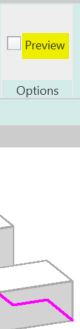
  • Tick the Preview checkbox
  • Aaaargh - it does not work when you adjust railing segment properties! It does not show the adjusted slope property.  You still have to Finish the sketch to see the effect


  •  Edit the path again
  • Select several segments to change their Slope property
  • Aaargh - the properties are not shown on the Option Bar when you select multiple segments!
  • Change the Slope properties for every alternate segment - one by one!
  • Finish the Path sketch

Something is wrong with the overall height of the railing when compared to the straight railing on the other side of the stair.  

  • This can be checked in an elevation view

Height Correction

To solve this, one way is to change the Height Correction property of each segment:
  • Edit the railing path again
  • Select the first segment
  • Change its Height Correction property to Custom; with a value to match the riser height
  • Finish the Path sketch
  • The railing height is now correct (more or less)
  • The lowest segment is now sloping

  • Check it in elevation


Now who has a headache?  Not just Revit!

This is a crazy amount of work to do in order to get this sort of correct.

Of course, you could avoid all this by just putting in a straight diagonal railing, but the point of this blog is to demonstrate the problems with stairs and railings - and to show workarounds (however nasty they may be).   There may also be situations where the diagonal railing is not appropriate - perhaps where the stepped sides are much larger steps.


Wednesday, 15 July 2020

Slanted Wall Joins in Revit 2021

Following on from my Analysis of Slanted Walls in Revit 2021, and Analysis of Slanted Walls and Rooms in Revit 2021 let us see how it handles slanted wall joins in plan.


Mysterious Behaviour

I have not yet figured out the rule for this, but it seems that slanted walls sometimes join properly in plan and sometimes not . . .

The failure of wall layers to join seems to occur at varying wall angles and different view range cut heights.


At gently slanting angles the problem does not manifest itself:
  • At 25 degrees (or less) with a standard wall cut height of 1200mm (or 4 ft for the imperialists), the wall joins ok

  • Bump the slant angle up to 30 degrees and it fails
    • In this example the base offset of the wall is raised 900mm above the Level that it is hosted on - that causes all kinds of issues, but it is not the problem here

  • Change the 'View Cut Plane Height' to 1000mm, and it works again - but of course the cut location of the wall changes

  • Change the angle to 45 degrees and it breaks again
  • It seems that the base height of the wall has no influence on this (providing it is below the cut height).

There must be some mysterious formula that combines the cut plane height with the wall slant angle that makes it work or fail!

Of course it should not fail at all - why doesn't it just work as expected?

Talking of "Course", this problem doesn't show up in Coarse views - only Fine and Medium detail levels.

Tuesday, 3 September 2019

Reveal Obstacles in Path of Travel - Revit 2020.1

Revit 2020.1 Enhancement

If you place a 'Path of Travel' using the new (in Revit 2020) feature, you may encounter a situation like that shown below, where the path appears to go through an object that should be an obstruction - such as the path through sofa example below:


In addition to other Revit 2020.1 enhancements to the Path of Travel feature  - Move Start/End Points, we have a new tool that may help you out:

Reveal Obstacles in Path of Travel -


This is useful for figuring out why your path of travel is not behaving as expected. 
  • On the Analyze toolbar, click on 'Reveal Obstacles'

  • This temporarily changes the view display to show in orange all categories that represent obstacles to the path.
In the example below (Autodesk sample file), some items are not shown orange
 
  • The doors are not obstacles because that category is excluded
  • Some furniture is not shown in orange (obstacle) because they are below the cut plane for calculation.  The reason is that the model is split level, and the living area is 500mm lower than the rest of the house - refer to Analysis Zone follow up for more detail on Split Levels and calculation heights.
  • In the case of the large sofa family, one part of the component shows orange - this is the high back.  This demonstrates that Revit actually analyses the geometry of elements, not just a bounding box for each component - which is a good thing.

As the sofa is much lower than the main floor level, only the back projects up into the analysis zone.
  • If the sofa is raised by 200mm (8"), then the sides of the sofa also project into the zone - they become obstacles, and hence turn orange (it may not be immediate - see glitches listed below).

However, the path itself does not change - you have to select it and click on 'Update Path' for that to happen;  then the path will go around the sides of the sofa.

Obstacle Settings

 
If you go the the Route Analysis Settings, you can add or remove obstacles by category - for example add Furniture and Casework categories to the list that are not obstacles


Initially nothing happens, but when you update the path it will no longer avoid those categories.  These will no longer be highlighted in orange by the 'Reveal Obstacles setting

Furniture no longer an obstacle

Casework category no longer an obstacle - path not yet updated

NB. There is some unexpected behaviour that can occur with the 'Reveal Obstacles' feature:
  • If you already have 'Reveal Obstacles' mode on when you go into the 'Route Analysis' settings, then change the categories - Reveal Obstacles does not update the categories displayed orange/grey (you need to turn it off then on again for a refresh).
  • If Reveal Obstacles mode is on, and you try to select an element:
    • Initially it will highlight all of the obstacles as one item;  select it and you get Analysis results Properties (see below for more details)
    • if you tab select, it highlights a component, but still considers it part of the analysis result;  Select it and you get Analysis Result listed but without any properties;
    • Tab again and it finally selects just the element - you can then change its properties;  However, the Reveal Obstacles highlighting is not updated even when it should be - eg. if the sofa height is changed to 500mm so that the whole sofa becomes an obstacle, the sofa does not turn orange (when it should).
  • If you select the whole analysis result, you get shown properties for the Analysis Result.
  • It is not immediately clear what these properties are for.
  • If you click on the 'Edit..' button (Results Visibility), as you would be tempted to do, you get some more mysterious properties
  •  Make the dialog box a fraction wider, and one of the headings shows in full:  'Analysis Display Style' - it has a hidden button to the right of <By View>

  • Click on the hidden button to reveal the Display Style dialog

  • You can play around with the text and arrowhead settings
 
  • And go to the Legend Tab
  • Click on 'Show Legend'
  • The end result means not much to me, but I'm sure it has a purpose
Arrowheads and legend displayed
  •  You can move the legend on the view, if that is what you need


I am guessing that these analysis display settings are for some other kind of analysis, but have been enabled here too?
  • I am not going down that rabbit hole today!
 

Conclusion

Sadly, useful as this new feature is, it does not address fundamental shortcomings - such as what you need to do when Revit fails to generate (or update) a path at all.

We need more help to be able to deal with that situation, as the Warning dialog box is not at all helpful!

Wednesday, 12 December 2018

Weird Railing Stuff - part 14 - Railing Baluster Height Top Offset

Balusters have always been completely confusing in Revit Railings.   However, one baluster property used to be quite straightforward:  the baluster Height, which Revit seemed to handle quite well - providing the baluster top constraint was set to the appropriate rail element.  In earlier Revit days, baluster height could be set as an absolute value, or could be attached to one of the rail elements:

Revit Railing Rail Element Definition


Each of the named 'Rails' were available as a top constraint for balusters - whatever names you gave to the Rails were shown in the drop-down menu 

In the old Revit railing method the highest 'Rail' usually represented a handrail or top support/fixing rail of some kind - and this would be a good constraint for the balusters - if its height changed, all the balusters would adjust accordingly.  It didn't really matter what you called the Rails (but it does matter now - see below).

A Cat Among The Pigeons

A few years ago, we were given new specialist system defined railing elements "Top Rail" and "Handrail".

The original rail elements remain available in the UI for use as mid rails for example (although can still be used to represent handrails).  This means there are now three different ways to define the continuous rail elements.

At this point, Baluster top constraints became very confusing and inconsistent . . . .

Baluster heights can still go up to the old Rail elements.  They can also go up to new 'Top Rail' Elements but not to new 'Handrail' elements. 

Some railings have only handrails without top rails, so that is a totally ridiculous restriction.

Rail Naming

The old style Rails, might have the same name ("Top Rail") as the new system name of "Top Rail", particularly as that was a common naming convention in old style railings.


This could be very confusing as they both appear in the Baluster dialog drop-down menu - in order to avoid a conflict  the word "Element" is added as a suffix to the system family.  This drop-down menu is the only place it is so named.  Get used to it!

What I recommend is to rename any old style Rails that may represent handrails or top rails - this will avoid any confusion. 


A better solution is to use the new system family rails for either handrails or top rails and then remove the old style rails that used to represent handrails.  Even though the new system Rail families have been available for at least five years, you will find many railings that are set up the old way, so you will need to fix them.  The reason for the old style railings hanging around so long is partly because old railings are not upgraded to new style ones when an old project or template is upgraded - this is amply demonstrated when you look at the Autodesk sample file, which has never been fixed!!!  Thankfully Autodesk did fix their supplied project templates - but your company templates need to be manually corrected.

* NB. The new style handrails/top rails are mostly better than the old ones - but not in every situation.  The old rails could go around a tighter corner on a half landing, where you have limited space [they both break but the older ones in a better way].  However, on balance I prefer to go with the new ones and live with that shortcoming and the many confusing inconsistencies built into them.

Warnings

When you do fix your old railings, and you replace old style handrails with new ones, you may get an error message when you delete old handrails/top rails:

When you try to delete an old rail from a railing definition, Revit may warn you that it will reassign the height reference (for balusters).  If you say Yes, you might expect Revit to make an attempt to resolve it.  This is in fact quite misleading, because it usually fails abjectly:


The balusters cease to exist until you go in and manually correct their top constraints, which will most likely be unassigned:

Confused by all this?  That is not surprising - go in to your project template and check all the railings, and it may start to make sense.