BILT Speaker

BILT Speaker
RevitCat - Revit Consultant
Showing posts with label edit. Show all posts

Tuesday, 8 February 2022

Stepped Handrail on Stepped Stairs in Revit

A couple of years back I posted on how to create a stair with stepped sides. 


I always intended to follow it up with what happens to the handrail, and how to solve it?  Well, it is never too late.


Just in case you are wondering how to create the stepped side to the stair run in sketch mode - here is a trick for creating a DIY array in Revit.


When you create a stepped boundary for a stair run, the handrail also becomes stepped, but it is pretty clunky.


Baluster Placement

The first thing to notice is the hideous baluster placement - it is placing one at each change of direction, and one (or more) in the middle of each segment.

To tidy it up:

  • we will probably have to create a new railing type (to avoid messing up the straight railing on the other side of the stair
  • then edit the railing type properties; and the baluster placement
  • Untick the checkbox for 'Use baluster per tread on stairs'


  •  Balusters will only be placed at ends of each segment

Alternatively you could try the opposite: keep the Baluster per tread, but remove the start and end balusters - but then you lose control of the baluster locations in the segments running parallel to treads (not centred).


Top Rail Properties

You may not like the clunky Art Deco look of the vertical "Gooseneck" handrail segments, so the first step is to tab-select just the top rail (not the whole handrail) - then look at its Type properties

  • Change the Transitions from 'Gooseneck' to 'Simple' (or None)
  • Revit will give a not very helpful "not continuous rail" warning:
  • Whichever you choose (Simple or None), you get 'None', as Revit has a headache and thinks it is all too difficult, so it simply can't be bothered to join the segments

Edit Railing Segments

The next thing to try is editing the whole railing path:

  • Select the handrail
  • Edit the path

  • Select the first path segment at the base of the stair
  • Check its properties, displayed on the Option Bar
  • Change the Slope from 'By Host' to 'Sloped'

  • Finish the Sketch
  • Nothing appears to happen to the railing slope!  We will solve that later.
  • Edit the path again
  • Select the next segment that should be sloping (3rd from end)
  • Change its Slope to 'Sloped'
 
This is getting tedious, so let us try a couple of shortcut:

  • Instead of finishing the sketch to see how it looks, you could try the cool new Railing "Preview" feature in the ribbon menu (in a 3D view)
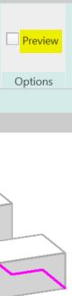
 

  • Tick the Preview checkbox
  • Aaaargh - it does not work when you adjust railing segment properties! It does not show the adjusted slope property.  You still have to Finish the sketch to see the effect


  •  Edit the path again
  • Select several segments to change their Slope property
  • Aaargh - the properties are not shown on the Option Bar when you select multiple segments!
  • Change the Slope properties for every alternate segment - one by one!
  • Finish the Path sketch

Something is wrong with the overall height of the railing when compared to the straight railing on the other side of the stair.  

  • This can be checked in an elevation view

Height Correction

To solve this, one way is to change the Height Correction property of each segment:
  • Edit the railing path again
  • Select the first segment
  • Change its Height Correction property to Custom; with a value to match the riser height
  • Finish the Path sketch
  • The railing height is now correct (more or less)
  • The lowest segment is now sloping

  • Check it in elevation


Now who has a headache?  Not just Revit!

This is a crazy amount of work to do in order to get this sort of correct.

Of course, you could avoid all this by just putting in a straight diagonal railing, but the point of this blog is to demonstrate the problems with stairs and railings - and to show workarounds (however nasty they may be).   There may also be situations where the diagonal railing is not appropriate - perhaps where the stepped sides are much larger steps.


Wednesday, 13 October 2021

Double-Click Trouble in Revit

In Revit 2019, one of the fantastic new features was the ability to slow double-click to rename views in the Project Browser !  

Fantastic?  Not true - it is an almost universally hated new feature.  If you search on the internet, you will find an endless list of questions and answers on how to disable this feature.

I do know one person (who shall remain nameless) who claims to like this feature - but they are only one amongst thousands (or even millions) who hate it.

Beta Testing

I remember reading about this feature during beta testing of Revit 2019.  Many of the testers pleaded with Autodesk NOT to roll this feature out, as we knew it would cause trouble.  However, it was too late - the code was already in the software.  Autodesk did relent somewhat, and offered us a way to disable it by editing the revit.ini file, to add the line (in the [User Interface] section):

SlowDoubleClickInProjectBrowser=0

Of all the many online descriptions of how to disable this feature, here is a link to one of them, written by Pieter Schiettecatte on Dan Stine's blog:

BIM Chapters 

Default Setting

Now why did Autodesk make the ridiculous mistake of making the default behaviour different from previous versions?  I would guess that it was to make the change "discoverable" - but it is very annoying that we have to actively disable it.

In contrast to this,  despite much pleading, Autodesk refuses to change one other default behaviour that causes much Revit-misery:

Why, oh why can't they make the "Little Button of Evil" disabled by default?  Yes, that is the "Drag Elements on Selection" setting.

More Double-Click Trouble

Another irritating double-click feature that was added in Revit 2013 was the ability to take you straight into the Family Editor when you try to select a component in Revit.  For various reasons this might register as a double-click - particularly when you try to edit a tag value, for example.  What a huge time-waster that it opens the Family Editor when you clearly do not want to edit the family.

 This was another feature that we asked them not to include after beta testing it - to no avail.

Again, Autodesk relented, but it was not until a couple of releases later (so we had to live with it for a while).

Now you can either edit the Revit.ini file or better still, go to the Revit Options to choose what double-click behaviour you would like.


These settings get saved into your Revit.ini file, so they can be rolled out to an organisation:

[UserInterface]
DoubleClickFamily=EditType
DoubleClickSketchedElement=EnterEditMode
DoubleClickViewOnSheet=ActivateView
DoubleClickOutsideViewOnSheet=DeactivateView
DoubleClickAssembly=EnterEditMode
DoubleClickGroup=EnterEditMode
DoubleClickComponentStairs=EnterEditMode


I prefer a Double-Click on a component to either do nothing or to 'Edit Type' - but never, ever edit the family.  That should only be done as a very conscious decision of right-clicking or clicking on a command on the Ribbon menu.


Saturday, 9 November 2019

Scope Box View Property Greyed Out in Revit

Here is a little software trick to catch out the unwary Revit user:

There are some situations where the Scope Box property of a view is greyed out - so you cannot assign a Scope Box to the view.

The answer may be to do with the Crop Boundary - and it may not be obvious, especially if the crop boundary is hidden.


To track this down:

  • Make the Crop Boundary visible
  • It may or may not be apparent that the  Crop Boundary has been edited
  •  Or it may not be obvious - if only a minor edit is done to the boundary
  • Select the crop boundary
 
  •  If it has been cropped, the Ribbon will show the 'Reset Crop' icon available
  • Another way to check if it has been cropped is to look for the shape-handles on the crop boundary - extra dots indicate segments in a boundary
  • Click on 'Reset Crop' - the edits to the boundary will be removed (along with the extra shape-handles)
  • The Scope Box property will now be available for use.
  •  The 'Reset Crop' icon will now be greyed out - indicating the crop is no longer edited.

This behaviour is quite logical once you know what is going on - but it can be confusing when you first encounter it.  Of course you do not want people to accidentally remove a Crop Boundary just by applying Scope Boxes - without realising what they have done.

Monday, 2 July 2018

Creating Revolves in Revit Mass - CME Part 3

This is part 3 of my series on  comparing the five traditional form creation tools with equivalent techniques in the Revit Conceptual Massing Environment.
Previously we analysed the creation of extrusion forms and Blends in the CME.  Now it is the turn of 'Revolves' (pun intended):


Part 3:  Revolves

Creating a Revolve in the Conceptual Massing Environment is relatively simple, but it does not give you the option to nominate the Axis of Rotation - you just have to draw a straight line and hope that Revit figures out which element you want to use as the axis:
  • Draw a straight line (for the axis of rotation) and a profile (closed or open) 

  • Select them both and ‘Create Form’ 
  • If the profile is closed it will just create the revolve (maybe!); 
  • If the profile is open, it will suggest two options: a revolve or a flat surface connecting the line and profile

  • A closed profile can allow a nested loop to create the form, but only if the profile is made from lines – not from a loaded family profile 
  • This is only one of two situations that I have found where you can include a loop within a loop during the 'Create Form' process in the Conceptual Massing Environment.

Once the Revolve has been created, the form will have properties for Start and End angle - these can be changed to reduce the form from a full 360 degree revolve.


YouTube

Below is a short YouTube description of the Create Revolve in CME process:


Monday, 25 June 2018

Creating Blends in Revit Mass - CME Part 2

An earlier post introduced the idea of  comparing the five traditional form creation tools with equivalent techniques in the Revit Conceptual Massing Environment.  Previously we analysed the creation of extrusion forms in the CME.  Now it is the next of the 5 traditional forms:


Part 2:  Blends

In the traditional Revit environment, you have to decide on a blend before you start.  In the massing environment you can do that or decide to create a blend after you have made an extrusion.  The exact method depends on how the profile is created before using it to generate a form.

I have recorded a video description of this process, available on YouTube.

This one is pretty quiet, maybe suitable for an open plan office.  Crank up the volume if you are at home.

Read on if you don't like videos (or you are hard of hearing!).

There are several ways to create a blend form in the CME:


Method A (Unlock Extrusion)

This method assumes that you already have a form created as an extrusion.
  • Select the form;
  • ‘Unlock Profiles’ (if locked)


  • This converts the form into a blend, which has a profile at each end (each the same to start with) – they can be edited separately.
If the original profile was model lines:
  •  Each profile can be edited in sketch mode (Edit Profile command).
 

If the profile was reference lines:
  • The start remains as reference lines, with limited edit capability (move the reference lines) 
  • The end profile can be edited in sketch mode

If the original profile was a component:
  • you can edit the end profile only, not the start profile
  • If the profile family is parametric, you can adjust the form parametrically
  • You can edit the profile family, and the form changes when you reload the family - within reason; if the changes are too drastic, it may fail when you try to reload.

Method B (Create Blend)

Create two parallel 2d profiles (model, reference lines or flat components) ;

  • Select both profiles; 
  • ‘Create Form’
  • Revit will create a Blend form

If the profiles were model lines:
  • You can edit the profiles of each end 


If they were reference lines:
  • You have limited edit capability (move lines)


If the original profiles were components:

  • You can change them (if parametric) 
 
  • Or you can edit the profile family and reload 


The two starting profiles do not need to be parallel.


Related topics: