BILT Speaker

BILT Speaker
RevitCat - Revit Consultant
Showing posts with label angle. Show all posts

Friday, 26 June 2020

Analysis of Slanted Walls in Revit 2021

Any new modelling feature in Revit is welcome.  Although I have seldom needed to slant walls in a Revit model, it something that people occasionally want to do.  Now that you can easily slant walls in Revit 2021, we can expect to see a huge number of very scary looking buildings going up around the world (and hopefully not falling down).  Builders and structural engineers will probably be cursing Autodesk for years to come for this new feature!

For the first time in many years I did not do any beta testing of this "Shiny new feature" of Revit - so I do not yet know of its limitations or benefits.  I decided to do some very simple testing to see what the software engineers came up with.  Here are my preliminary findings:

Slanted Wall Angles

Once you place a wall in Revit 2021, it has a new property:
  • "Cross-Section" - this will be set to "Vertical"


Change the property to "Slanted" and it enables another new property:
  • Angle From Vertical
  • The angle will initially be set to zero

In a section view you can see the wall angle zero being vertical
  • In this example there is a room in section to the left of the wall
    • selected wall is purple
    • Room in section is pink
    • There is a vertical reference plane where they meet (green dashed line, not yet visible)
    • There are several detail lines (dashed) running from the base of the wall (inside face) up at 10, 30 and 45 degrees to vertical.

Wall Pivot

I was curious about the wall pivot point:
  • Set the angle to 30 degrees
    • Notice the edge of the room has moved back from the reference plane;
    • The wall pivot point is not the bottom left corner (inside face of the wall);
    • The inside face of the wall is not on the detail line.
  • On checking I realised that the wall 'Location Line' property was set to Wall Centerline
    • The wall is pivoting around its centreline base of wall
    • This is fair enough - but is a setting to watch out for
    • It becomes more obvious when the angle increases to 45

  • The wall thickness does not change but the horizontal dimension across its base line increases with the angle.


It is unlikely that you would want the wall centreline to be the rotation point as it is hard to predict where the inside face base will be from its original location (unless you resort to trigonometry).

To solve this:
  • Set the angle back to zero
  • Change the Location Line to 'Inside Face of Wall' (or Outside face if you want)

  • Change the angle and it will rotate around the inside face base of wall
    • Room edge stays on the original reference plane
    • Wall edge aligns with the slanted detail line

Change the angle again and it pivots as expected

So far, so good - even if a little tricky.
  • Behaves as expected, but is a trick for new players.

Base Offset

What happens when you change the base offset of the wall?
  • Try changing the base offset to 1 metre (1000mm)

  • Oops - the wall is still pivoting down at the level - not the base of the wall (ie. around where the wall base would be if it started down at the base constraint level).
    • That is very confusing

  • What happens if you combine a base offset and a wall centreline Location Line?
    • The end result will be almost unpredictable
    • The room extent is nowhere near the actual wall

I do not believe that this is the correct behaviour for the wall - I think it should pivot about the base offset height at whatever Location Line you have chosen.
  • This is really going to confuse people

[Edit - Plan Views added]

The diagrams above show what happens to the wall in section, so I have added a few snapshots of plan views to clarify (I hope) what to expect:
  • Vertical wall
  • Inside face of right hand wall on the reference plane
  • Right hand wall Slanted 45 degrees; Location Line Inside face; zero base offset
    • Note that base of wall has not moved (on the reference line):
  • Right hand wall Slanted 45 degrees; Location Line Wall Centreline; zero base offset
    • Note that the inside face of the base of the wall has moved slightly to left (in fact whole wall has moved) - due to pivot point being centre of wall):

  • Right hand wall Slanted 45 degrees; Location Line Inside Face; 700mm base offset
    • Base of wall moved 700mm to right
    • Apparent wall location is the same as the wall with zero base offset - but that is what happens at the cut plane height only (a notional drawing convention).  The important thing is that the base of the wall should not move when you slant the wall, but it does.


Conclusion:

Should I have done some beta testing and warned the software developers that this was not acceptable behaviour?

I have tried that with several new features in the past - sometimes they have modified things accordingly, but often not.  Often the beta testing process comes too late in the development cycle, and things like that cannot be changed before release.

Either way, I think it is wrong and should be fixed immediately - before people start using it on real projects.  Slanted walls will be scary enough without being built in completely the wrong location.

Next blog post I will be investigating slanted walls and room extents

And following that, 'Why the wall joins don't work in plan' . . . .


Monday, 1 April 2019

Stepped Steps in Revit Stairs


I had a question recently about how to create a Revit stair that is stepped in plan?  It is actually not that hard to do but the method is not so intuitive - so here are some instructions:

Tapered Stair

For the record, we'll start with a tapered stair, to get the methodology - as that is very easy:
  • Create a stair with a straight run
 
  • Select the run (in stair edit mode)
  •  Convert the run to a sketch 
 
  • Select the run and 'Edit Sketch'
 
  • Adjust the angle of one or both sides
 
  • No need to trim the riser lines (providing the boundary lines up with the end risers
  • Finish the sketch and the stair


Stepped Stair

Follow a similar process as the tapered stair to start with:

  • Create a stair with a straight run
 
  • Select the run (in stair edit mode)
  • Convert the run to a sketch - this stage is not reversible, so you need to be sure about it
 
  • Select the run and 'Edit Sketch'
  • The sides and back of each step need to be drawn as 'Boundary Lines', which show green in the sketch mode [Refer to Poor Man's Array for a tip on how to do this]
  • As per the tapered stair, the riser lines do not need to extend out to the boundary lines - this makes it easier to sketch and to modify later
 
  • Finish the sketch and the stair


You may get some interesting results with the railings, but that can be dealt with in the next blog post . . . . Stepped Handrails in Revit


Monday, 2 July 2018

Creating Revolves in Revit Mass - CME Part 3

This is part 3 of my series on  comparing the five traditional form creation tools with equivalent techniques in the Revit Conceptual Massing Environment.
Previously we analysed the creation of extrusion forms and Blends in the CME.  Now it is the turn of 'Revolves' (pun intended):


Part 3:  Revolves

Creating a Revolve in the Conceptual Massing Environment is relatively simple, but it does not give you the option to nominate the Axis of Rotation - you just have to draw a straight line and hope that Revit figures out which element you want to use as the axis:
  • Draw a straight line (for the axis of rotation) and a profile (closed or open) 

  • Select them both and ‘Create Form’ 
  • If the profile is closed it will just create the revolve (maybe!); 
  • If the profile is open, it will suggest two options: a revolve or a flat surface connecting the line and profile

  • A closed profile can allow a nested loop to create the form, but only if the profile is made from lines – not from a loaded family profile 
  • This is only one of two situations that I have found where you can include a loop within a loop during the 'Create Form' process in the Conceptual Massing Environment.

Once the Revolve has been created, the form will have properties for Start and End angle - these can be changed to reduce the form from a full 360 degree revolve.


YouTube

Below is a short YouTube description of the Create Revolve in CME process:


Tuesday, 3 April 2018

Accurately Rotate a Section in Revit

When you have a non-orthogonal building model in Revit, you often need to create sections (or elevations) at various angles other than orthogonal.  Normally you would want sections to be perpendicular/parallel to the angled model elements - the image above shows a section somewhat off parallel (much exaggerated version of a typical example where it may be slightly off).

If the section is not exactly perpendicular (or parallel) to objects in the model you can encounter some very frustrating problems:
  • You may not be able to dimension sectioned elements
  • 2D Symbolic lines in families may not show up (eg. door swing in elevation)
If you try to rotate the section to make it exactly perpendicular (or parallel) to objects in the model, it is not as easy as you might expect:
  • One thing to avoid is measuring an angle and then typing in the measured angle during the rotate process - it is never accurate enough, even if you use several decimal points.  Revit is extremely fussy about this - even a difference in angle of 0.000001 degrees may be enough to play havoc with dimensions and symbolic lines.
  • It is much more accurate to rotate by snapping start and end rotation points to the section to be rotated and some other reference element.  The other problem you will encounter is an inability to snap to section lines.

Workaround

The trick here is two preparatory steps
  • Create a reference plane snapped to the section tail end, and exactly parallel to the angled wall
  • temporarily turn off the section markers at the ends of the section line - use the little cycle symbols et each end of the section.  Then you can accurately snap to the section line when rotating. 


To rotate the section:
  • During the rotate command, snap the centre of rotation to the point where the reference plane and section tail end meet (they must meet exactly)
  • Snap the start of the rotation to the section head end
  • Snap the end of the rotation to the other end of the reference plane


The section should end up exactly perpendicular (or parallel) to objects in the model.  Unfortunately the annotation on the section will have moved (much exaggerated in this example), so you may need to do some tidy up, and replacement of dimensions.
  • Don't forget to turn the section head/tail marker back on.

You should now be able to dimension to sectioned elements, and the 2D symbolic lines in families should now be visible.

It is your call as to whether it is worth rotating the section line or just create a new section - it all depends on how much annotation there is, and how often the section has been referenced in other views.

Once you have the section oriented exactly right, you surely don't want to lose it, so most likely you will pin it in place.  Revit is very annoying in that you cannot change the 2D extents of a pinned section (as you can with datums like grids).  Wouldn't it be nice to be able to pin a rotated section and have it never move again, but still be able to adjust its 2D extents per view, without unpinning it.  If you would like that, please go to the Revit Ideas forum and vote for 'Allow us to change 2D extents of pinned sections'


[Edit:  Now we have a new way to do this in Revit 2019.1, which has an 'Align Section' functionality, using the existing 'Align' command. ]

Monday, 2 October 2017

Weird Railing Stuff - part 8 - Moving Handrail Supports

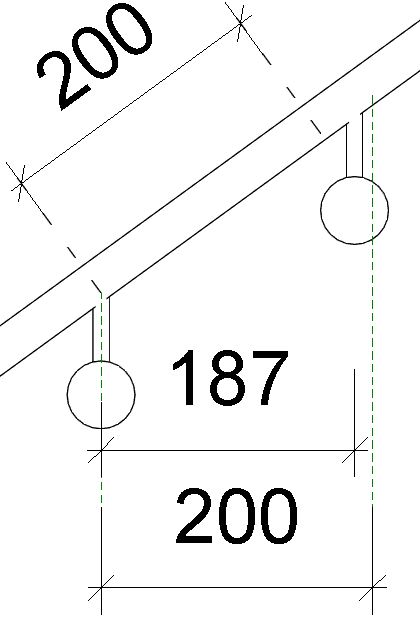
I have explained previously that Revit handrail support spacing is measured along the length of  sloping handrails, not horizontal (plan) distance.

What does this mean when it comes to moving individual supports on a handrail?  Well, the rules are equally weird, but differently weird.

In the following  example, you might want the spacing to be measured horizontally (in plan), so you need to move the supports on the sloping parts of the handrail.

The first thing to do is select just the support (Tab, select), and unpin it.  This will allow you to slide the support along handrail - but most likely you want to be very precise about how far it is moved.  You might try using the 'Align' tool, providing you have something like a reference plane to align to:

Law of Diminishing Returns


In this context, the Align tool does not do what you expect - it presents you with more Revit Weirdness.  Once you select the reference plane to align to, then click on the support centreline, it moves the support only about two-thirds of the way (this fraction probably varies depending on the slope of the railing). 


My first thought was that it was converting the horizontal distance to an actual distance up the slope of the handrail - but it is not that value (something slightly different).  It is using some other mysterious mathematical rule that I cannot fathom.

If you try Align again, it goes another two-thirds of the remaining distance.

 Try again and you get closer - but you will never quite get there.  There has to be a better way?

Move Weirdness

If you try using the 'Move' command, and select a horizontal distance, you get exactly the same result as the Align tool - it does not move it to where you tell it.  The same 'Law of diminishing returns' applies.

The Move (Workaround) Solution

The trick here is to use the move command, but make sure that you snap to the end point of the support, and then have a reference line that has an end (or intersection) point exactly where you want it to be placed - slightly above the underside of the handrail.

The Slide (Workaround) Solution

There is another trick - providing you have a (reference) line running vertically and stopping exactly where you want it to be placed (as with the previous workaround), you can just select it and slide it along the handrail, and it will snap to the right place.  However, I do not recommend this because if your reference line is too long or short, it may look like it went to the right spot but could be slightly off.  The move command is more precise.

Reset Warning

If you click on the 'Reset Rail' or 'Reset Railing' commands, you will lose all of those careful support relocations on the whole handrail - each moved support would be moved back and repinned, while deleted supports would be reinstated (including those silly ones exactly on the ends of handrails).


More on this subject: