BILT Speaker

BILT Speaker
RevitCat - Revit Consultant
Showing posts with label align. Show all posts

Monday, 2 October 2017

Weird Railing Stuff - part 8 - Moving Handrail Supports

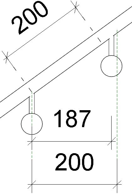
I have explained previously that Revit handrail support spacing is measured along the length of  sloping handrails, not horizontal (plan) distance.

What does this mean when it comes to moving individual supports on a handrail?  Well, the rules are equally weird, but differently weird.

In the following  example, you might want the spacing to be measured horizontally (in plan), so you need to move the supports on the sloping parts of the handrail.

The first thing to do is select just the support (Tab, select), and unpin it.  This will allow you to slide the support along handrail - but most likely you want to be very precise about how far it is moved.  You might try using the 'Align' tool, providing you have something like a reference plane to align to:

Law of Diminishing Returns


In this context, the Align tool does not do what you expect - it presents you with more Revit Weirdness.  Once you select the reference plane to align to, then click on the support centreline, it moves the support only about two-thirds of the way (this fraction probably varies depending on the slope of the railing). 


My first thought was that it was converting the horizontal distance to an actual distance up the slope of the handrail - but it is not that value (something slightly different).  It is using some other mysterious mathematical rule that I cannot fathom.

If you try Align again, it goes another two-thirds of the remaining distance.

 Try again and you get closer - but you will never quite get there.  There has to be a better way?

Move Weirdness

If you try using the 'Move' command, and select a horizontal distance, you get exactly the same result as the Align tool - it does not move it to where you tell it.  The same 'Law of diminishing returns' applies.

The Move (Workaround) Solution

The trick here is to use the move command, but make sure that you snap to the end point of the support, and then have a reference line that has an end (or intersection) point exactly where you want it to be placed - slightly above the underside of the handrail.

The Slide (Workaround) Solution

There is another trick - providing you have a (reference) line running vertically and stopping exactly where you want it to be placed (as with the previous workaround), you can just select it and slide it along the handrail, and it will snap to the right place.  However, I do not recommend this because if your reference line is too long or short, it may look like it went to the right spot but could be slightly off.  The move command is more precise.

Reset Warning

If you click on the 'Reset Rail' or 'Reset Railing' commands, you will lose all of those careful support relocations on the whole handrail - each moved support would be moved back and repinned, while deleted supports would be reinstated (including those silly ones exactly on the ends of handrails).


More on this subject:

Sunday, 22 March 2015

Revit Moves With Nearby Elements Command

I was recently looking at ways to streamline the production of Area Plans in Revit - in particular how to keep them up to date as the model changes.  I found some interesting behaviour when using Revit's 'Moves With Nearby Elements' command - a very under-used capability.

Many Revit experts do not like to use this command because the end results can be very unpredictable.  I figured it might be worth trying to make it more predictable by documenting its behaviour.  But first, an analysis of why you might use this command instead of other methods of locking things in Revit - in particular Area Boundary Lines locked to walls:

Locking Area Boundary Lines in Revit

  • When you first create an area plan, it asks if you want to 'Automatically create area boundary lines associated with all external walls?'  - I always say NO to this because it almost certainly won't end up with what I want.
  • Then when you start placing Area Boundary Lines, it assumes that you want to 'Apply Area Rules' - presumably these are USA based area measurement rules?  It has a checkbox in the options toolbar that is always ticked.  This drives me nuts as I always have to untick it, as I do NOT want my area lines locked to the centreline of walls

  • I would normally use the 'Pick Lines' tool, so I can pick wall edges.  At this stage you have the option to lock the lines to the wall edges so they will move when the walls move (in the Option Toolbar).  Conventional Revit wisdom says that for Area Boundaries, you should not tick this box because you would end up with way too many explicit constraints in the model - any changes to the model have to check the explicit constraints, and if you have too many your model gets bogged down.  In addition, any changes to the model that conflict with explicit constraints will evoke warning messages, and may even prevent you making the changes [the worst example of this is when sketch lines inside a floor or ceiling are locked to walls and impossible geometry stops you in your tracks].
  • Using the 'Align Tool' and then locking Area Boundary lines to walls would have similar issues - way too many constraints, potentially hundreds for each area plan.  Such locks should be reserved for a few very important constraints.
  • 'Moves With Nearby Elements' is an implicit kind of locking - the relationship is controlled by a set of (somewhat mysterious) system rules, rather than a user defined relationship.  However, the rules are not as simple as "moves with nearest appropriate wall" - it does depend on the order of placement or moving of elements, and also the timing of setting the 'Moves With Nearby Elements' property, so Revit must be storing some kind of information about "when" the implicit relationships came into being [it would be great if someone from the 'Factory' could comment].  I will try to explain this later.
My current workflow for Area Boundaries is to place the lines using the pick line tool, but not set up any locks.  Then there is always a checking/updating process to be performed before printing drawings or exporting area schedules - a lot of aligning boundary lines to walls needs to take place.  Not ideal, but common practise.

But why not use the 'Moves With Nearby Elements' method?  It could take care of the majority of updates without bogging down the model - making the checking process much faster.  If you use this method, you need to understand the rules and bugs.


When to use 'Moves With Nearby Elements'

Firstly, this functionality is wrongly named - it should be 'Moves With Nearby Walls', as that is what it does, and the Revit help file states:
"Use the Moves with Nearby Elements option to specify that lines and components near a wall move a corresponding distance whenever that wall is moved"

It is only available for certain Revit elements: 
Revit help rather unhelpfully states that:
"Only straight lines that are parallel to a wall are affected by this option. It is not available for detail lines, sketch-based elements, and families"  -
  • what is the difference between components and families in this context?
  • In fact it does work for parallel arcs (not just straight lines), as described in the next line of the help notes.


It does work for:
  • some external families (components) - non-hosted only (but not all categories)
  • model lines, 
  • Room separation lines, 
  • Area boundaries,
It does not work for:
  • Hosted external families (face-hosted, floor, wall or ceiling hosted etc)
  • Work plane based external families
  • Columns and structural column families
  • Adaptive components
  • System families (walls, stairs, railings etc)
  • Sketch lines within system families
  • In-Place families (even if they contain a reference plane), despite the fact that the properties palette has the check-box available (but option toolbar does not) 
  • Detail components or lines
  • Annotation of any kind (symbols, tags,  regions etc)

How to use 'Moves With Nearby Elements'


When placing an eligible component or lines, the properties palette will have a checkbox for 'Moves With Nearby Elements' - so you can set it before placing elements.


You can also select an element(s) and apply the setting by ticking the same checkbox in the properties palette after the element has been placed.

In addition to this there is a checkbox that appears on the options toolbar when you select an element that is eligible for this setting.  In theory it makes no difference which checkbox you tick, it should apply the rules to the selected element(s).  In reality there are some bugs to watch out for (see below).

To see what actually happens when you apply this setting, as well as my take on the rules that they follow refer to my post on The Rules

Bugs in 'Moves With Nearby Elements'

There are three bugs in the software that I know of - each making this feature seem even more unpredictable in its operation:

Bug 1
In Revit 2013 and earlier, if you selected already placed elements and applied the setting using the checkbox in the properties palette (dialog box), then the setting just plain did not work.  If you ticked the checkbox in the options toolbar, it did work.  once applied there is no way of telling which checkbox was used.   I reported this bug to Autodesk a few years back, and I notice that this has been fixed for most element types in v2014 and later.

Bug 2
I just discovered that in Revit 2015, the bug described above had still not been fixed for Area Boundary lines and Model Lines.  I have reported this but it is not likely to be fixed for a while yet.  The rule here is that you should either tick the checkbox before placing the Area Boundary lines, or else use only the options toolbar for selected area boundary lines.

Bug 3
Not sure if this is a bug or just a UI inconsistency - In-Place families have the checkbox only in the properties palette, not on the Options toolbar.  Regardless of whether it is supposed to be there or not, the setting does not work.

For more information on this feature refer to other posts:
- Non-Hosted external Families
- Moves with Nearby Elements - The Rules

Tuesday, 21 January 2014

Revit Stair Landings - Part 2: Modification

In the previous post I talked about creating stair landings in Revit.  Now its time to look at modifying landings, which is very different to the old sketch method (pre-v2013).

Stair landing components can be modified individually but they interact with run components in unexpected ways, so you need to learn the rules as it is not always intuitive. If stair landings have been created by the new sketch method or have been “converted”, then the interaction with runs is more limited.

To modify a landing component you generally need to be in edit stair mode. The exception to this is changing landing properties, which can be accessed by tab-selecting the landing without editing the stair.  There are various methods to modify a landing, each with their own benefits.  There are also some subtle differences between landings in v2013 and v2014 (and later), to be described further on:

 Align Tool

The Align tool will behave differently depending on what you select to align and what the relationship is between linked components.

  • if you align a landing edge, it will most likely move the landing, which in turn will move the associated runs, in effect moving the whole stair
 
  • If you align a run edge, it will move that run. If there is a linked landing, it will also move the edge of the landing, changing its size; it will not move the next run
 

  • NB. Align does not work on the centreline or edges of a curved stair

Move Tool

If you use the Move Tool on a landing (in plan), it will also move the connected run components; on a simple stair with one landing connected to two runs it will effectively move the whole stair;  on a more complex stair the end result depends on the other connections (see later)

Simple Stair


If you want to move just the landing but keep first/last riser locations, you have to use some reverse logic by moving the whole stair then adjust the risers back. 
  • You can use the Move command on the landing component, or select the two runs and move those – either way the effect is the same. 
  • You then have to drag the arrow shape handle at top or bottom of the stair to return the risers to their original location, and Revit will automatically add/remove risers from the connected run


Complex Stair (multiple landings)

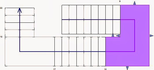
If the stair has two or more landings, then the intermediate run will be connected to both landings.  The knock on effect of moving one landing would be to move the free run but not the intermediate run (which is attached to the other landing);  the end result is to change the landing shape or size:
In this example the landing is selected and moved to the right and it automatically changes from rectangular to L-shaped.  The free run at the base of the stair moves, but the intermediate run cannot move - so the landing has to change shape to remain attached.
The rule to understand here is that when a landing is moved in plan its height cannot change thus something else has to give (its shape and/or attached run locations).

Move Run to Adjust Landing Shape

Another "not so intuitive" workflow is to use the Move Tool on an attached run component to adjust the landing shape.  In this example the run is moved in order to add a stagger into the landing so that both runs no longer align.

 
Revit v2014 has additional shape handles on the landing, which allow alternative more intuitive workflows to achieve this (see below).

Move Landing in Section to change stair layout

Stair layouts can be changed in section or elevation too.  The landing height can be changed by moving it up or down to resolve headroom issues - it will snap to the nearest multiple of riser heights, so you don't need to calculate the exact amount to move it by in order to maintain equal risers.  Revit will move the run start/end points to suit.


Shape Handles

For general information on stair shape handles refer to my previous blog post on the topic.  However, that does not cover landing shape handles, which are a little more confusing. In addition, the original v2013 landing shape handle behaviour was changed for v2014.

The landing height can be adjusted by using the arrow shape handles on adjacent runs.  The number of risers on one run will be reduced, while the other is increased, thus changing the start and end locations of the stair without moving the landing in plan:

NB. Do not use the filled dot shape handle at the base of the stair, unless you really want to change the height of the start of the stair.

You can use a side arrow shape handle to make a landing width greater than that set by adjacent runs, but it will not let you make it less.
Once a landing is wider, that offset is sometimes maintained if an adjacent run width is changed - but not always.  It seems unpredictable.

Revit v2013

In v2013, landing shape handles are fairly limited in what can be achieved.  On a rectangular half landing (U-shaped stair) there are 4 shape-handles.  
If you want to stagger the runs where they meet the landing, it seems natural to select the landing and try to adjust it using the shape handle where the landing joins the runs. It won’t let you drag the handle towards the runs, only away from them. But this actually gives a different result - it cuts a notch and it moves the outside of the landing and to maintain its  depth (although it may be a desirable outcome in some situations).  To achieve a stagger in the landing we must move one of the stair runs towards the left (described previously).


Landing Width/Depth

Modifying adjacent run widths will affect the aligned landing width.  Landing sides will continue to align with runs unless you over-ride that using the landing side shape handles.
In v2013 it may also affect the depth too, but the rules are tricky:  changing a run width will only affect the landing below the run, not above it.

The rules seem random until you test it systematically as shown below:

Revit v2014 Shape-Handles

In v2014, landing shape handles have been improved, but at the same time the automatic control of landing depth has been broken - this is something you need to watch out for.  Additional shape-handles are available between each run and adjoining landing.  This allows you to put a stagger into a rectangular landing more intuitively by dragging the landing shape handle (rather than relying on moving a run).

 
The shape handle in the stair well works similar to v2013 in allowing you to put a recess cutout into the landing.  However, in v2014 it will not maintain the landing depth - but it does give a warning message that the "depth is less than run width".  This warning is triggered by Revit comparing the landing depth with the smallest actual width of either attached run, not the minimum run width set in the stair type properties (actual width can be made smaller than the minimum required).
Fortunately the landing depth can be corrected with temporary dimensions or the outer shape handle.  NB. the inside shape handle will not snap to any increments or give a temporary dimension, so you need to put in a reference plane to snap to before correcting the landing depth.

Landing Width/Depth

Modifying adjacent run widths in v2014 will only affect the landing width but not the depth.  This may be logical if you make one run wider, but if you make both/all runs wider you would want the landing depth to match - but it won't, so you have to manually alter all landings, meaning it is only too easy to get a landing depth that is smaller than the narrowest run. The outside line of the landing will only change if the outside shape-handle is explicitly moved.

Landing Properties

Landing heights can be changed in the properties dialog box - you need only type in an approximate value and Revit will correct it to the nearest multiple of riser heights.  This will not move the landing in plan, so the end result will be that adjacent runs will alter to accommodate the new landing height.
Landings do not have Width or Depth instance properties, so you can only adjust those dimensions by:
  • Change the adjacent run widths;
  • Move adjacent runs;
  • Use the shape handles; 
  • Temporary landing depth dimension (v2014 only)
  • Convert to sketch (not advisable).

Temporary Dimensions

  • Landings do not have any temporary dimensions when selected in v2013.
  • Landings do have landing depth temporary dimensions when selected in v2014.
  • Spot dimensions can be placed on landings in plan and section/elevation, but they cannot be used to adjust landing heights

Convert to Sketch

Automatic landings can be converted to sketch landings so that you can modify the plan shape to something that is not possible to create using automatic landing features.  Automatic landings can form a wide variety of shapes, but cannot:
  • Have rounded corners
  • Have notches cut out of outside corners (only in stairwell)
Convert to Sketch should be the last resort, and should be avoided where possible.  This is irreversible - the only way to make a landing revert to automatic behaviour is to delete and place a new one, which would remove any attached elements, modifications or annotation.
Once a landing is converted to a sketch:
  • It will never have shape handles;
  • It will never adjust in plan when adjacent runs are moved;  
  • it will cause error messages requiring landings and runs to unjoin if an attached run is forced to move away from the landing;
  • It will allow height adjustments

Tips and Tricks

  • If you want to change the landing width it is better to change the adjacent run widths to control it automatically (unless you don’t want them to align).
  • In Revit v2014 it allows the landing extent/depth to be smaller than the narrowest run width. To fix this you can use the shape handles on its outer edge or the temporary dimension.
  • in v2013, landings do not have handles where it meets a run, so you can’t use shape handles there - to stagger the risers for example; you have to MOVE a whole run to achieve that. 
  • Be careful with the Move command on landings because it will most likely affect adjacent runs, and may end up moving the whole stair.
  • If you have created a top landing, any changes to the adjoining run below it may not be able to flow through to the top landing (as it cannot change in plan) and it may give you a message about "stairs and landing cannot be joined".
  • The quickest way to change a stair layout might be to change a landing height property - this can be done without even editing the stair